RCI 2950DX Image Rejection Modification
As noted in the review, an anomaly, not found in other radios, was found in two of the RCI 2950DX tested.
Further test determined signals outside the passband of the 10.965 crystal filter were indeed getting
through or around this filter. All the components and every circuit trace was followed per the schematic
diagram. No component failures were found. In addition, no visible faults were found with the circuit board
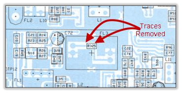
following the schematic diagram. However, the circuit board diagram indicated a resistor R325 location
under FL3, the 10.965 crystal filter.
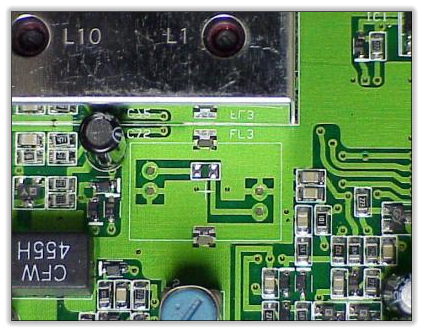
Removing FL3 was more difficult than anticipated due to the double sided circuit board. Once removed, the
R325 location was revealed and empty. Testing the radio with the filter removed showed the same image
problem was encountered. Probing the area of R325 with test equipment indicated the sensitivity of the
circuit. The closer test probes got to the pads of this resistor, the higher the signal strength on the radio
LCD meter. This concluded the remedy needed.
As explained in the RCI 2950DX review, Ranger Communications could not duplicate this problem. This
means they do not acknowledge this problem. No doubt this will not be covered under warranty. In addition,
if not properly done, it may indeed void the warranty. The following modification portion of this article
describes and illustrates how to perform the modification, but due to the double sided printed circuit
board, it is very difficult to remove the FL3 crystal filter without damaging the circuit board! THE
FOLLOWING PROCEEDURE SHOULD ONLY BE DONE BY A QUALIFIED TECHNICIAN WITH
EXCELLENT SOLDERING SKILLS!!! CB World Informer or the author cannot be held responsible for
any damage or loss of warranty!
Now that I've scared the the stuffing's out of you, lets get back to the mod so you understand what was
done to the test radio.. As mentioned above, this is a double sided circuit board. The heavy ground plane is
where the most difficulty will be found. It requires a great deal of heat to melt the solder on the other side of
the board in order to remove it with an extraction tool. A high wattage soldering iron used for only as long
as necessary should be used. That's where the experience comes in. If you leave the iron on too long the
circuit board will burn and the traces will lift of the board. Even if it's patched up, if noticed during a warranty
repair, RCI may deem the radio out of warranty and then you're SOL. In addition, if there is still solder
holding the filter and you pull it out only to find it's missing a pin or two, ditto! Please leave this one to the
professionals.
All radios that incorporate this main circuit board have been and will continue to be modified by
Bob's CB & Wireless prior to sale at no additional charge. If you own a RCI 2950DX, 2970DX,
2985DX, 2990DX, Bob's CB & Wireless offers this modification at $25.00.
http://www.bobscb.com/contact.htm
As described above, the crystal filter FL3 must be removed. There are two traces from R325, one connects
to the input of the filter and the other connects to the output of the filter. Both traces can be pealed up using
a xacto-knife. Remove the resistor pads and traces back to the filter connections cutting the traces off at
the crystal filter pads. See diagram and photos below.
FL3 Section Of Circuit Board Diagram
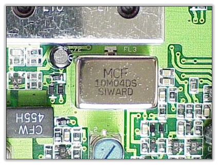
FL3 Component Side Of Circuit Board.
FL3 Removed From Circuit Board.
R325 Traces Removed From Circuit
Board.
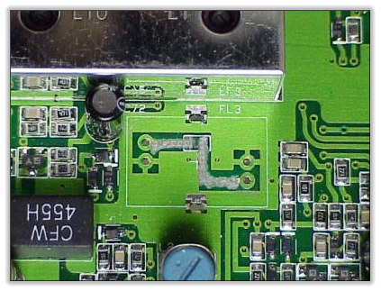
Once the traces are cleanly cut, the monolithic crystal filter can be reinstalled. Test and reassemble radio.
Tuning is not necessary.
Bob F

© CB World Informer Network 1996 - 2023 Worldwide Rights Reserved

September
2001 Web
Edition


- August 1996
- September 1996
- October 1996
- November 1996
- December 1996
- Review Of Midland 79-290 AM/SSB Mobile
- Cobra/Uniden SSB Chassis Mod UPDATE
- Clarifiers
- President Jackson Unlocked Clarifier Mod.
- Cobra 148 & Uniden GrantXL Clarifier Mod.
- Cobra 142GTL & Uniden Washington Clarifier
- Uniden Grant Unlocked Clarifier Mod.
- Uniden PCI22 PRO SSB Clarifier Mod.
- Review Of The Northstar DX880HL
- Big Bust At The Consumer Electronics Show
- Bob's CB Has Opened
- January 1997
- The New Mongoose Model 450 Review
- Wilson Antenna Tests The Trucker 5000
- A Company With Interference Solutions
- Solving Telephone RF Interference
- Lowpass Filters: What, Where, And How
- Using Highpass Filters For TVI
- How To Conduct A Noise Audit
- Modern Do-It-Yourself Grounding Techniques
- Using Water Pipes For RF Grounding
- Using Water Pipes For RF Grounding
- February 1997
- The New Emperor TS-3010 Review
- Bulkhead Grounding
- Grounding Coaxial Cable Shields
- Using Anti-Oxidants
- Modern Lightning Protection - RF Entry Ports
- Modern Lightning Protection - AC Power Lines
- Modern Lightning Protection - Control Lines
- Modern Lightning Arrestors - Polyphaser VS I.C.E.
- Modern Lightning Arrestors - Alpha Delta VS I.C.E.
- Modern Lightning Arrestors - Cushcraft VS I.C.E.


- July 2001
- Galaxy DX 2547 Reveiw
- Inside The DX 2547
- DX 2547 Channel Mod
- DX 2547 Clarifier Mod
- DX 2547 Photos
- DX 2547 Manual Excerpts
- The Anttron Story
- Anttron 305 Revisited
- New Antrron Products
- Aries A-SWR 460 Digital Meter
- Barjan Buys Wilson Antenna
- Wilson Electronic In Cell Phone Market
- First Web Issue
- Help Get The Word Out
- August 2001
- Sneak Preview: The New Maverick A24
- Maverick A24 Front Panel Controls
- Maverick Conversion
- Inside The Magnum Maverick A24
- Barjan Buys Francis Antenna
- Wilson Antenna, 1 Year After Barjan Buyout
- CBer Busted
- Astaic's MobileMax
- Solarcon I-Max 2000
- False Performance Claims
- CAUTION: Don't Burn Out That Radio
- Magnum's Filtered Power Cord
- Dragon Super Heavy Duty SO-239 Stud
- CBWI...Give Us Your Opinion
- September 2001
- Reveiw Of The RCI 2950DX
- RCI 2950DX Image Rejection Modification
- RCI 2950DX Coversion & Clarifier Mods
- RCI 2950DX Photos
- RCI 2950DX Board Component Layout
- RCI 2950DX Adjustment Layout
- RM-9807: Petition To Remove 155 Mile Limit
- Slip-Seat Radio Box
- RF Limited UTB-1 Adjustable Talkback Board
- A Message From The Editor
- October 2001
- November 2001
- December 2001
- January 2002
- February 2002
- July 2002
- June 2014


