In This Issue
Emperor TS-3010 Review
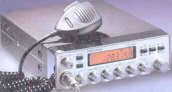
This is the newest arrival from the makers of Emperor
radios. It's a 4 watt AM 12 watt SSB rig. The first radio
released to the US by Emperor was the TS-5010, an
upgraded copy of the President HR-2510. The new TS-
3010 has the look of an updated Cobra radio. The
display is LCD with a six digit display/counter. This is a
unique feature, the first four digits are a direct display
the same as in the HR-2510, RCI-2950 etc. and the
last two digits (1KHz and 100Hz) are a frequency
counter which changes as the clarifier is moved. This comes in handy finding center slot or running even
frequencies on SSB, say 5Khz. down from channel 36 or 27.3600Mhz.
I'm not sure whether they were shooting for a type accepted CB or a Amateur radio. It is modifiable from
the front panel. One mode is 40 channels including "A" channels. The other mode comes up in the
Amateur band on 28.315Mhz. in band F. Turning the channel selector automatically runs you through the 7
bands from 25.615 Mhz. to 28-755 Mhz. In either mode it could present a problem for dealers in this
country. They have a second version, not released release yet, that powers up on 10 Meters in the 28.315
Mhz to 28.755 Mhz band. This would be a legitimate 10 Meter Amateur radio. The second mode of
operation has 8 bands ranging in frequency from 25.165 Mhz. to 28.755 Mhz. In both versions of the radio
the channel and alternate channel mode is obtained by pressing the Meter and Tone buttons at the same
time for I second. Dealers be ware! Don't openly sell this as you would a HR-2510 or any other 10 Meter
rig. In it's present version you won't have a leg to stand on if Uncle Charlie visits.
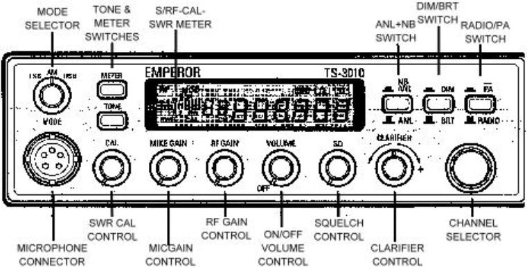
This is a nice looking rig. The face of' this radio is brushed aluminum with chrome knobs and bezel. The
mic connector is conveniently located in the front. All but the channel selector knob have pointers
protruding beyond their edges but the pointers would be more functional if they were painted a color that
would stand out from the chrome. One thing puzzles me, their placement of the front panel controls. The
volume is the forth control from the left and like most operators I'm use to it being either the first or second
from the left.
Inside the radio I found the quality to be very good. Immediately I noticed the clean design and absence of
the usual wire harnesses. I counted a total of 18 interconnection wires including and this includes the two
speaker wires. The rest of the interconnecting wiring is done through ribbon cables minimizing obstructed
view of the main board. Once the covers are off the removal of the face bezel is easy and can be done
without removing any more screws. All that's need is to remove the eight knobs and lift six clips while
sliding the face off. The CPU board, mounted in the face of the radio, can be removed by taking out two
screws and unplugging three ribbon cables. Then by sliding the CPU board up it can be removed form the
series of interlocking tabs and separated form the radio. The boards are well marked with signal names
and component designators. This is a real plus for technicians. I know it really helped me while I was
working on it. I'm in the process of getting a service manual for the TS-3010. All the improvements I made
were without a schematic and my changes may be fine tuned once I see the circuitry in it's entirety.
Bench and on air test showed the receiver AM/SSB sensitivity and selectivity is about average for this type
radio. Sideband did overload on strong signals similar to the President Jackson before modification. I was
able to cure this with two added component and one value change in the AGC circuit. The stability is pretty
good, it only changed about 250 Hz. from cold to warm. The clarifier is locked as usual. I'm happy to say
this is the first radio I've operated with a mechanical rotary encoder channel selector that couldn't be
fooled. It didn't jump extra channels or change them in the, wrong direction when the channel selector was
rotated very slowly or quickly. The transmitter has clean audio on both AM and Sideband before and after
peaking.
There is a drawback on this display/frequency counter. The third digit doesn't change when, you go up
5Khz. If you're on 27.4050 and go up 5Khz. the display will read 27.4000 not 27.4100. If you run on even
frequencies you'll just need to keep that in mind. I tried to get the radio to drop 5KHz. This would have
solved the display problem but it didn't work out.
Despite the problems I've uncovered the TS-3010 is a good radio. For the cost of a Uniden Grant XL with
channels you can have the Emperor with a six digit display/counter and 3 times the channels. I wish they
made provisions in the CPU for 5Khz channel steps. It would have been easy because the rig uses a
PLL0305A chip which can be stepped in as low as 100Hz increments. The rig is setup for a UP/DOWN mic
but the stock mic is a very small dynamic type with no room for buttons. The HR-2510 mic, has the. same
wiring and the UP/DN buttons will change the channels without changing anything. An Astatic 575M6
works dynamite and there is room for UP/DN push button switches. Also a battery back-up is used to
retain the last frequency used. The radio is well made and is the best sideband radio in the $240 price
range with these features. I hope the factory addresses the problems I've found and comes out with a
5Khz. channel step version of this rig. If they do this I'm sure this will become the #1 radio in sales.
The following are changes that I made to the Emperor TS-3010:
Correcting The SSB Receiver Overload Problem
1.
Change C28 from .001 µf to .47 µf 16 volt.
2.
Add a IN4148 diode in series with R48 band side to IC 2 pin 2.
3.
Add a .03 µf capacitor from IC 2 pin 2 to ground.
Correcting Excessive Delay On Receive After Transmit
1.
On the solder side of main board change the 100 µf capacitor under the relay RL-1 to 47 µf 16
volts.
Unlocking And Expand The Clarifier To A Range Of +7Khz. To -2Khz.
1.
Remove the knobs, face and CPU board.
2.
On the CPU board ground the low side of the clarifier potentiometer.
3.
On the CPU board cut the trace on the high side of the clarifier potentiometer.
4.
On the CPU board connect the high side of the clarifier potentiometer to constant 8 volts and
replace CPU board.
5.
On the main board remove D67.
6.
Set the clarifier control to the (-) position marked on the face.
7.
On channel 40 USB adjust L41 until you read 27.4050 on the display.
8.
On channel 40 AM adjust L40 until you read 27.4050 on the display.
9.
On channel 40 LSB adjust L42 until you read 27.4050 on the display.
Tune Up Transmitter To 5 Watts-16 Watt Swing On AM & 20 Watts SSB.
1.
Remove R128 560W resistor (better swing on AM).
2.
Change R162 from 4.7KW to 2KW (more transmit audio on AM & SSB).
3.
Move L22 away from the driver transistor.
Transmitter Output Controls
VR10 AM modulation
VR5 AM Carrier
VR4 SSB ALC
©
CBWI


© CB World Informer Network 1996 - 2023 Worldwide Rights Reserved


AUGUST
VOLUME 1
ISSUE 7


- August 1996
- September 1996
- October 1996
- November 1996
- December 1996
- Review Of Midland 79-290 AM/SSB Mobile
- Cobra/Uniden SSB Chassis Mod UPDATE
- Clarifiers
- President Jackson Unlocked Clarifier Mod.
- Cobra 148 & Uniden GrantXL Clarifier Mod.
- Cobra 142GTL & Uniden Washington Clarifier
- Uniden Grant Unlocked Clarifier Mod.
- Uniden PCI22 PRO SSB Clarifier Mod.
- Review Of The Northstar DX880HL
- Big Bust At The Consumer Electronics Show
- Bob's CB Has Opened
- January 1997
- The New Mongoose Model 450 Review
- Wilson Antenna Tests The Trucker 5000
- A Company With Interference Solutions
- Solving Telephone RF Interference
- Lowpass Filters: What, Where, And How
- Using Highpass Filters For TVI
- How To Conduct A Noise Audit
- Modern Do-It-Yourself Grounding Techniques
- Using Water Pipes For RF Grounding
- Using Water Pipes For RF Grounding
- February 1997
- The New Emperor TS-3010 Review
- Bulkhead Grounding
- Grounding Coaxial Cable Shields
- Using Anti-Oxidants
- Modern Lightning Protection - RF Entry Ports
- Modern Lightning Protection - AC Power Lines
- Modern Lightning Protection - Control Lines
- Modern Lightning Arrestors - Polyphaser VS I.C.E.
- Modern Lightning Arrestors - Alpha Delta VS I.C.E.
- Modern Lightning Arrestors - Cushcraft VS I.C.E.


- July 2001
- Galaxy DX 2547 Reveiw
- Inside The DX 2547
- DX 2547 Channel Mod
- DX 2547 Clarifier Mod
- DX 2547 Photos
- DX 2547 Manual Excerpts
- The Anttron Story
- Anttron 305 Revisited
- New Antrron Products
- Aries A-SWR 460 Digital Meter
- Barjan Buys Wilson Antenna
- Wilson Electronic In Cell Phone Market
- First Web Issue
- Help Get The Word Out
- August 2001
- Sneak Preview: The New Maverick A24
- Maverick A24 Front Panel Controls
- Maverick Conversion
- Inside The Magnum Maverick A24
- Barjan Buys Francis Antenna
- Wilson Antenna, 1 Year After Barjan Buyout
- CBer Busted
- Astaic's MobileMax
- Solarcon I-Max 2000
- False Performance Claims
- CAUTION: Don't Burn Out That Radio
- Magnum's Filtered Power Cord
- Dragon Super Heavy Duty SO-239 Stud
- CBWI...Give Us Your Opinion
- September 2001
- Reveiw Of The RCI 2950DX
- RCI 2950DX Image Rejection Modification
- RCI 2950DX Coversion & Clarifier Mods
- RCI 2950DX Photos
- RCI 2950DX Board Component Layout
- RCI 2950DX Adjustment Layout
- RM-9807: Petition To Remove 155 Mile Limit
- Slip-Seat Radio Box
- RF Limited UTB-1 Adjustable Talkback Board
- A Message From The Editor
- October 2001
- November 2001
- December 2001
- January 2002
- February 2002
- July 2002
- June 2014


