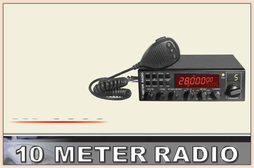


Congratulations
Your new Top Gun Quad-5 all mode 10 Meter Transceiver is engineered to provide you with top performance and
features of radios costing much more. The QUAD-5 can only bring you all this using SMT technology which guarantees
the best stability, reliability ,unprecedented quality and the latest up to date technology components. Your new All Mode
multi-functional QUAD-5 radio is a new step in personal communications providing features not found in radios costing
much more. Although many programable features are accessed through the front panel, we provide the computer to
radio programming cable for advanced programming ability. To ensure you get the most benefit from this radio, please
carefully read this manual before installing and using your QUAD-5 radio.
Go to www.TopGunTec.com for the programming software download.
Thank you for purchasing a
Top Gun Technologies
product.

Top Gun Technologies


CONTENTS
FUNCTIONS & FEATURES...............................................................................................................................................................1
WARNING..........................................................................................................................................................................................1
RESET FUNCTION (Resume Factory Default)...............................................................................................................................1
INSTALLATION.............................................................................................................................................................................2 - 4
HOW TO USE YOUR RADIO
.......................................................................................................................................................4 - 8
FUNCTION MENU SETUP
..........................................................................................................................................................8 - 11
OPERATING PROCEDURE TO RECEIVE........................................................................................................................................11
OPERATING PROCEDURE TO TRANSMIT.....................................................................................................................................11
SPECIFICATIONS..............................................................................................................................................................................12
T
omorrow's Technology Today


1


FUNCTIONS & FEATURES
Large
LCD which displays frequency and all types of information.
1.
DUAL-DIGITAL
LED Readout
F
or CHANNEL
DISPLAY.
2.
USES EL (Electro-Luminecent) technology for backlight.
3.
4.
All Mode: PA, CW, AM, FM, USB, LSB modes
A
5.
,
B
,
C
,
D
,
E
,
F , 6 bands in total, with 60 channels at most in
each band to be programmed.
4
Frequency
Tuning Steps 10HZ, 100HZ, 1KHZ or 10KHZ.
6.
Multiple CLARIFIER Operating Modes.
7.
8.
Flexible menu functions and PC programming software* to meet
varied customer demands. PC - Radio programming cable included.
ECHO Function
with adjustable delay and
adjustable
volume
controls.
9.
SQ, ASQ Function (FM and AM mode only)
10.
RF GAIN ADJUSTMENT
11.
RF PWR ADJUSTMENT
12.
SCAN FUNCTION
13.
RB FUNCTION
14.
NB/ANL FUNCTION
15.
DW DUAL-WATCH FUNCTION
16.
BEEP PROMPT
17.
+10KHZ Function
18.
19.
SWR S/RF Input DC Voltage display function
TOT function
(Transmitter
Out
Timer)
20.
HI-CUT Receiver Tone FUNCTION
21.
EMG CALL
22.
SWR PROTECTION
23.
POWER SUPPLIED VOLTAGE PROTECTION
24.
Key-Lock Function
25.
WARNING
To use the radio, please connect the antenna to location "B" on the back
panel of the equipment first
and then set the antenna SWR
(Standing
Wave Ratio) before communicating.
F
a
i
lure to do so may result in the destruction of the power
amplifier,which is considered abuse and is not covered
by the warranty.
RESET FUNCTION (Resume Factory Default)
This Radio
i
ncludes a RESET FUNCTION to set all features to
the factory default settings in case some functions are changed
a
n
d
y
ou
d
o
n
o
t
k
n
o
w
h
o
w to resume normal settings. The Radio will
resume factory default once this function is activated.
How to Operate:
Step 1: Power off the radio.
Step 2:
Press and hold FUNC and SCAN keys at the same time,
followed by powering on the radio.
Step3: Release the two keys when LCD displays "RES".
All former settings will be replaced by Factory Default value when
LCD displays "REND" .
WARNING: All former settings will be replaced by Factory Default
values after operating the RESET
FUNCTION.
Top Gun Technologies
*Go To www.TopGunTec.com For Programming Software Download


2


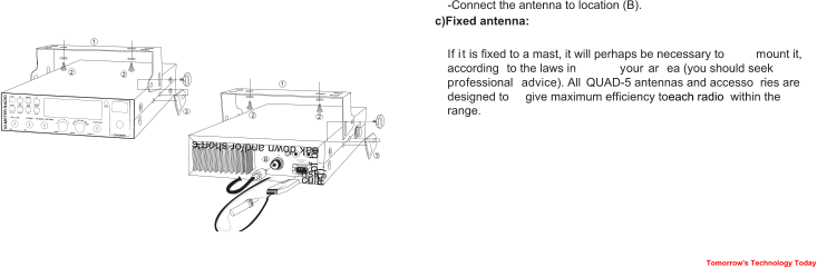
INSTALLLATION
WHERE AND HOW TO MOUNT YOUR RADIO
1.


a)
You should choose the most appropriate location
from a simple
and
practical point of view.
b)Your radio
should not interfere with the driver or the passengers.
c)
R
e
member to route wires and cables (e.g.: power, antenna,
accessory cabling) so that they do not in any
way interfere with the
driving of vehicles.
d)
To install your equipment, use the supplied bracket (1) and the
self-tapping
screws [2] provided (drilling diameter 5
mm). Take
care not to damage the vehicle’s electrical system while
drilling the dash board.
e)
Do
n
o
t
f
o
r
g
e
t
t
o
insert the rubber joints [3] between the radio and
i
t
s support as these have a shock-absorbing effect which permits
gentle orientation and tightening of the radio.
f)
Choose where to place the microphone hook and remember that
the microphone cord must stretch to the driver without interfering
with the controls of the vehicle.
ANTENNA INSTALLATION
2.
a)
Choosing your antenna:
F
o
r
r
a
d
i
o
s
,
t
h
e
l
o
n
g
e
r
t
h
e
antenna, the better its results. Your
dealer will help you with your choice of antenna b) Antenna Mobile.
b)Mobile antenna:
surface (ground plane) , away from windshield mountings.
-There are two types of antenna: Pre-Set Antenna which
should
be
used
on a good ground plane (e.g. car roof or lid of
the trunk),
and Adjustable Antenna which offer a much larger
frequency
range and can be used on a smaller ground plane.
For an antenna which must be fixed by drilling, you will need a
good contact between the antenna and the ground plane. To obtain
this, you should lightly scratch the surface where the screw and
tightening star are to be placed.
Must be fixed to the vehicle where there is a maximum of metalic
A fixed antenna should be installer in a space as clear as possible.


3


WARNING:
Never replace the original fuse (10A) by one of a different
value.
4.
BASIC OPERATIONS TO BE CARRIED OUT BEFORE USING
Y
O
U
R
RADIO FOR THE FIRST TIME
(
without transmitting or
u
s
i
n
g
the <<Push-To-Talk>> switch on the microphone)


ADJUSTMENT OF SWR (Standing Wave
Ratio)
5.
WARNING:
This must be carried out when you use your radio for
the first time (and whenever you re-position your antenna). The
adjustment must be carried out in an obstacle-free area.
Adjustment with an external SWR meter
a)
To connect the SWR meter
Connect the SWR meter between the radio and the antenna as
close as possible to
the radio (use a maximum of 18" cable).
b)To adjust the SWR meter
-Set the radio to channel 20@D band in FM.
-put the switch on the SWR meter to position CAL or FWD.
-Press the <<Push-To-Talk>> switch on the microphone to
transmit.
Bring the needle to the mark by using the calibration key.
-
Change the
switch
to position SWR (reading of the SWR level).
The reading
on the
meter
should be as near as possible to 1. If
this is not the case, re-adjust your antenna to obtain a reading
as close as possible
to 1.( An SWR reading between 1 and 1.8 is
acceptable
, 1.5 or lower is most desirable
).
-It will be necessary to re-calibrate the SWR meter after each
adjustment of the antenna.
HOW TO USE INTERNAL SWR METER
6.
a)Connect the microphone
b)Check the antenna connections
c)Turn the set on by turning the volume knob clockwise
d)Turn the squelch knob to minimum
e) Adjust the volume to a comfortable level
f)Go to channel 20@D band by using either the UP or DN key on
the microphone or the rotary knob.
Y
o
ur
R
ADIO is protected against
reverse polarity. However,
b
e
f
ore
s
w
i
t
c
h
ing
it on, you are advised to check all the connections.
Y
o
u
r
e
q
u
i
pment must be supplied with a
continuous voltage of 12
v
o
lts (A). Today, most cars and
trucks are negative
ground. You
can
check
this by making sure that the negative terminal of the
battery is
connected either
to the engine block or to the chassis. If
this
is not the case, you should consult your dealer.
WARNING:
Heavy equipment generally have two batteries to
s
upply a voltage
of 24 volts, in which case it will be necessary to
insert a 24/12 volt
c
o
n
v
e
r
t
e
r
i
n
t
o
the electric
al
circuit. The
f
o
l
l
o
w
i
n
g
c
onnection
s
t
e
ps
should be carried out with the power
cable disconnected from the set.
a)Check whether the battery is of 12 volts.
b)
Locate
the positive and negative terminals of the battery (+ is red
a
nd – is black). Should it be necessary to lengthen the power
cable, please use the same or a
larger guage
of cable.
c)It is necessary to connect your
radio
to a permanent (+) and (-).
We advise you to connect the power cable directly to the battery
(as the connection of the cable
to the wiring of the car-radio or
other parts of the electrical circuit may, in some cases, increase
the possibilities of interference).
d)
C
o
nnect the red wire through a fuse
(+) to the positive
t
erminal of the battery
and the black (-) wire to the negative
terminal of the battery.
e)Connect the power cable to
your radio.
POWER CONNECTION
3.
Top G
un T
echnologies

4

-Set to channel 20@D band in FM.
-Press <<push-to-talk>> button on the microphone to transmit. The
LCD will display SWR value which should be as close as possible to
1. If this is not the case, re-adjust your
antenna to
obtain a SWR
v
alue as close as possible to 1 (a SWR reading between 1 and
1.8 is acceptable
, 1.5 or lower is desirable
).
HOW TO USE YOUR RADIO
10K:
Appears when +10KHZ function is usted.
EMG:
Appears when EMG channel is used.
SWR:
Appears when SWR is used.
SRF:
Appears when S/RF is used.
SC:
Appears when SCAN is used.
P
A
,
CW
,
AM
,
FM
,
USB
,
LSB:
Indicate different operating modes.
Appears when CLARIFIER function is FINE operation.
1.
Appears when CLARIFIER FUNCTION is COARSE operation or
2.
RT operation.
Appears when CLARIFIER FUNCTION is transmitting frequency
3.
regulated.
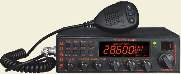
<FRONT PANEL>
OFF/ON/VOLUME(Inner Dual Concentric)
1.
T
u
rn clockwise to switch on the
r
adio and set desired vol
u
m
e
l
e
vel.
U
n
d
e
r
normal operating
conditions, the VOLUME control is
u
s
e
d
to adjust
the
output volume obtained either by the transceiver
s
p
e
a
k
e
r
o
r
t
h
e
external speaker or the external PA speaker, if used.
SQUELCH (Outer Dual Concentric)
2.
This control is used to cut off or eliminate receiver background noise in
the absence of an incoming signal. For maximum receiver sensitivity,


<LCD Display>
7 digits: Display frequency and any other information.
Indicating bars: Indicate RX, RSSI, PA, PWR, SWR.
The first decimal point: Appears when current
channel is edited with
SCAN DEL.
FUNC:
Appears after pressing FUNC key.
AQ:
Appears when ASQ function is started (only for AM/FM).
RB:
Appears when Roger Beep function is started (enabled).
NB/ANL: Appears when NB/ANL function is started (enabled).
BP:
Appears when BP function is started (enabled).
ECHO:
Appears when ECHO function is started (enabled).
VOIC: Appears when VOIC function
i
s
started.
Only
available
in
the
VHF
v
ersion
of
this
radio.
HI-CUT:
Appears when HI-
C
UT receiver tone
function is used.
DW:
Appears when DW ( Dual Watch) function issued.


CHANNEL


Tomorrow's Technology Today


5


RF POWER (Outer Dual Concentric)
6.
Adjustment of the output power is for AM and FM mode only. Reducing
the power is allowed when communicating with a person who has no
RF GAIN. The normal position of this function is set to maximum, fully
clockwise.
BAND SELECTOR
7.
Rotate this switch to select A, B, C, D, E, F band of operation
MODE(PA/CW/AM/FM/USB/LSB)
8.
This switch allows selecting the modulation mode PA, CW, AM, FM,
LSB or USB. Your modulation mode has to correspond with the one
of your correspondent. The mode selector changes the mode of
operation of both transmitter and receiver simultaneously.
Frequency Modulation/FM: for nearby communications on a flat
open terrain
Amplitude Modulation/AM: Communication on varying terrain and
obstacles in medium
distance.
Upper and Lower Side Band/USB-LSB: Used for long distance
communications (according to the propagation conditions).
This is frequency tuning knob which can be set as different modes
(refer to CLA Specifications in Functions Menu for more details).
PUSH
10.
This is PUSH Key which can be set as different modes (refer to PSH
specifications under Functions Menu for more details).
CHANNEL SELECTOR
11.
R
o
t
a
t
e
t
h
i
s
switch to select any desired channel. The selected
channel appears
on the LED directly
above the channel selector
knob.
CHANNEL INDICATOR
12.
Numbered LED indicates the selected channel to operate on.
RECEIVER/TRANSMIT INDICATOR
13.
When it is receiving, the LED will be green. The LED will be red when
it is transmitting.
LCD DISPLAY
14.
Display frequency, all types of information and icons.
FUNC
15.
This is function key. Press and hold this key for 2
seconds to enter
into Functions Menu Setup (refer to Functions Menu for more details).
Press FUNC key and other individual key to realize the second
f
u
n
ctions silk-screened under the
button. For example, press FUNC
k
ey followed by pressing RB key
to realize the BP function.
Press
FUNC key followed by DW to realize the LCD OFF function.
Detailed operations are as follows:
Pr
e
s
s
F
UNC key, "FUNC" icon will appear on LCD display. Release
This
control is used to control intervals of echo sound. (delay)
RG GAIN ( Inner Dual Concentric)
5.
This switch is for adjusting sensitivity during reception. For long
distance communications
RF GAIN should be set to maximum. RF
GAIN can be reduced to avoid distortion, when your correspondent is
close by and when he does not have RF POWER. The normal setting
of this function is on maximum (fully clockwise).
CLARIFIER
9.
it is desirable that the control be adjusted only to the point where
the
receiver background noise or ambient background noise is
eliminated.
Turn
fully
counter-clockwise then slowly clockwise until
the receiver noise
d
isappears. Any signal to be received must now
b
e
slightly stronger
t
h
a
n the average received noise. Further
c
l
o
ck-wise rotation will
increase the threshold level which a signal
must overcome in order to
be heard. Only
v
ery
s
t
r
ong signals will be
heard at a maximum clockwise setting.
ECHO
(Inner Dual Concentric)
3.
This
control is used to control echo volume effect. (amount of repeat)
TONE (Outer Dual Concentric)
4.
Top Gun Technologies


6


the
FUNC key, and then press other keys to realize the second
functions
silk-screened under the button. "FUNC+ Keypad name" is
to be used in the following operating instruction.
ROGER BEEP OR BEEP FUNCTION
16.
(1) RB
Press "RB" key to enable "ROGER BEEP" function with "RB" icon
appearing on LCD display. Press the key repeatedly to switch on/off
the function.
When RB function is enabled, the radio will automatically transmit the
audio signal at the end of your transmission. The listener can note
easily that your transmission is over through the signal.
(2) FUNC+RB
Press FUNC+RB to realize BP Function. It is a prompting function with
"BP" icon appearing on LCD display. Speaker would emit a BEEP for
prompting when press any key. press FUNC+RB repeatedly to switch
on/off the function.
NB/ANL or LOCK
17.
Press NB/ANL key to enable NB/ANL function with "NB/ANL" icon
appearing
on
the LCD display. Press the key repeatedly to switch on/
of
f the function.
N
o
i
s
e Blanker/Automatic Noise Limiter. These filters allow
re
d
ucing background noises and some reception interferences.
FUNC+NB/ANL
Press FUNC+NB/ANL to realize the Keyboard Lock function. When
this function is enabled, all keys are invalid except PTT, BAND
S
W
I
T
C
H
,
and MODE SWITCH. When pressing any key except PTT,
BAND SWITCH, MODE SWITCH, the LOCK icon will display on the
L
C
D
.
This indicates that the keyboard has been locked. Press
FUNC+NB/ANL
repeatedly to switch on/off the function.
DW or LCD OFF
18.
The DW (dual watch) function allows automatic alternate
monitoring of two channels. Refer to the following procedures to
enable this function.
T
o enable the DW fun
c
t
ion, first turn the
S
Q
control clockwise
until the background noise is cut out. Select the first channel to be
monitored by using the CHANNEL SELECTOR knob or the channel
selector keys on the microphone. Press the DW key and the DW icon
will flash on the LCD display. Secondly, follow the above procedures
to select second channel to be monitored. Finally, press the DW key
again and the two monitoring channels will be alternately indicated on
the LCD. Radio will automatically start monitoring (scanning) the two
channels. When a signal is detected on one of the channels, scanning
stops and it is possible to listen the communications on that channel.
Press PTT to transmit on this channel. If there is no transmission
or detected signal on that channel within 5 seconds(time to resume
scanning can be programmed by PC software), radio will resume
scanning. When the DW function is enabled, the DW icon appears on
the LCD. To exit the DW function, press the DW key or the PTT
key
.
T
h
e scan Type above is the SQ mode under SCA Selection in
Function Menu. If TI mode is selected and valid signal is detected, the
r
a
dio would still start scanning when it is time to resume scanning,
whether there is signal or not in current channel.
FUNC+DW
W
h
e
n
t
h
i
s
f
u
n
ction
is enabled, LCD display will be switched
OFF(LCD OFF).
Repeat this operation to switch ON/ OFF the function.
SCAN OR Scan.list
19.
SCAN
Automatic Scanning of busy channels.
Press the SCAN
key to enable t
he SCAN functio
n
. Before enabling the
noise is cut out. Then press the SCAN key, the radio will
a
u
t
omatically
scan all channels con
tinuously in the scan list and the
S
C icon will appear on the LCD. When a signal is detected on a
c
hannel, scanning stops on this channel.
Tomorrow's Technology Today
SCAN function, first turn the SQ control clock-wise until the
background


7


Y
ou will receive and also, can
transmit on t
h
is channel by pressing
P
T
T
k
ey. If there is no transmission or detected signal on that
channel within
5
seconds
(time
to resume scanning
can
b
e
p
rogrammed by PC soft
ware), radio will start scanning again. To
exit the SCAN function, press the SCAN key or the PTT key
.
T
he Scan Type ab
ove is the SQ mode under SCA Selection in
Function Menu.
If TI mode is selected
and valid signal is detected,
the
r
adio would still start scanning when
i
t is time to resume
scanning,
whether there is signal or not in current channel.
FUNC+SCAN
SC.LIST
(Scan
ADD or Delete).
Press FUNC+SCAN to delete current
c
hannel from
scan list.
The first digit on LCD would display.
When
S
c
a
n function is enabled,
t
he radio would skip the deleted channel.
Repeat this operation to Add or Delete channels from scan list.
20.
+10KHz or HI-CUT
+10KH
z
Press this key to shift frequency up by 10KHz.
When
pressing this key, 10KHz would appear on LCD and frequency
of cha
nnels is shifted up by 10 KHz. Repeat this o
p
e
r
a
t
i
on to switch
ON/OFF this function.
FUNC+ +10KHz
Press FUNC+10KHz to realize HI-CUT function. Once this function is
e
n
a
b
l
e
d
, the radio would cut out
high frequency interference. Its use
depends on reception conditions.
W
hen this function is enabled, "HI-CUT" would appear on LCD. Repeat
this operation to switch ON/OFF the function
SWR OR TOT
21.
SWR
When pressing this key, “SWR” icon would appear on the LCD. When
transmitting, SRF bars indicate SWR value other than PA or PWR
value. One bar displaying on the LCD indicates that SWR value is
1.0. Each additional bar indicates every 0.1 added value. Repeat this
operation to switch ON/OFF the function.
FUNC+ SWR
Wh
e
n pressing this key, TOT ON or TOT OFF would display on the
LCD for 2 seconds. Repeat this operation to switch ON/OFF the
f
u
n
ction. Whe
n ON a
p
pears o
n
t
h
e
LCD, use
r
s
c
a
n press P
T
T
to
t
ransmit. Then, the radio will time the transmitting duration.
O
n
c
e
the duration is beyond the set TOT time (programmable),
the
radio
w
o
u
l
d
emit
s
ound prompt and stop transmitting and back
t
o
receiving
state automatically. This function aims to protect the
radio
against
power transistor damage from superheating caused by
long transmission or microphone malfunction
.


<Rear Panel>
Accepts 13.8V DC power cable with built-in fuse (10 Amp) to be
connected.
POWER
23.
EMG OR S/RF
22.
EMG realizes Emergency Channel Call. When emergent situation
h
a
p
pens, th
e radio would switch to the channel set in advance to
communicate immediately
. Then the "EMG" icon would display on the
LCD . Press EMG key again to return to previous channel.
FUNC + S/RF
S
/
R
F
i
s
the switch of TX's or RX's S/RF indicating
. bar. When this
function is enabled, "SRF" icon will display on the LCD. Repeat the
this operation to switch ON/OFF the function.
Top Gun Technologies

8

EXT SP or PA SP
24.
EXT
SP
A
ccepts 4 to 8 ohm, 4 watt or higher external speaker to be
c
onnected. When external speaker is connected to this jack, the
built-in speaker is
automatically disconnected.
PA
SP
I
t is used to connect a PA speaker. Before operating PA, you must
connect a PA speaker to this jack.
ANTENNA
25.
Accept 50 ohm coaxial cable with a type PL-259 plug to be connected.
CW KEY
26.
<PRESS—TO—TALK—MICROPHONE>
The receiver and transmitter are controlled by the Press-To-Talk
switch on the microphone.
Press the switch to transmit and then release it to receive. When
transmitting, hold the microphone two inches from the mouth and
speak clearly in a normal “voice”. The radios come complete with low-
impedance (150 ohm) dynamic microphone.
PTT
1.
Transmitting key, Press to speak and release to receive a message.
UP/DN
2.
These key allow increasing or decreasing a channel number.
AQ
3.
(1)When the radio i
s
receiving a call,
press this key to en
able
ASQ
(Automatic Squelch Control) function. Then, "AQ" will appear on the
LCD. Press this key repeatedly to switch on/off the function.
(2)When the ra
dio is receiving a call, press and hold d this key for
o
v
e
r
2
s
e
c
o
n
d
s
t
o
e
n
a
b
l
e
s
ignal monitoring function. At the moment,
whether the
radio receive signal or not,
the radio would detect current
c
h
a
n
n
e
l to check whether current channel has weak signal.
R
e
lease AQ key to exit this function.
(3)Pressing PTT and AQ key at the same time,
t
h
e radio would
emi
t
a single-tone. This tone is to help and remind two sides of
c
ommunication to adju
st frequency
. The frequency o
f
t
his tone is
adjustable.
(4)ASQ (Automatic Squelch Control)
A
S
Q control setting. It has same fun
c
t
i
o
n
with AQ button on the
microphone.


This jack is for Morse code operation; To operate, connect a CW
key to this jack and place the MODE switch in the CW position (LCD
display icon "CW")
MICROPHONE
4.
The radios come complete with low-impedance (150 ohm) dynamic
microphone.
FUNCTION MENU SETUP
The initial functions and parameter can be changed via the following
settings and operations. Please read the following instruction before
making any desired amendments.
T
o enter Function Menu:
With the radio on, press and hol
d FUNC key
f
or
more than 2 seconds, and then release the FUNC key to enter into
the
Function Menu Setup. Under this condition, press FUNC key to
select
different functions menu,
use the
CHANNEL SELECTOR
Switch to
change the data of Function Menu.
Tomorrow's Technology Today


9

(1) STP (Frequency Tuning Step)
This menu is to set tuning step when adjusting frequency by
CLARIFIER knob
Options:
10HZ
,
100HZ
,
1KHZ
,
10KHZ
Default:
10HZ
(2) CLA (CLARIFIER knob functions setting)
This menu is to set functions turned by CLARIFIER knob. Options are
as follows:
FIN:
Fine regulation. When this option is selected, users can fine
tuning the receiving frequency by rotating the CLARIFIER
knob. In tuning process, the transmitting frequency can not be
regulated by the knob and “1” icon will appear on the LCD.
RT:
When this option is selected, users can regulate the frequency of
both transmitting and receiving. In tuning process, “2” icon will
appear on the LCD.
T:
When this option is selected, users can only regulate the
transmitting frequency. In tuning process, “3” icon will appear on
the LCD.
Default:
RT
COA: When this option is selected, press PUSH and turn CLARIFIER
knob to operate
COARSE function.
When pressing this key, "2" icon will appear on far left of the
LCD. Under this condition, rotate the CLARIFIER knob to change
frequency of both transmitting and receiving.
T:
When this option is selected, press PUSH and turn CLARIFIER
knob to change transmitting frequency. When pressing this key,
"3" icon will display on the far left of the LCD. Under this condition,
rotate the CLARIFIER knob to change the transmitting frequency
only.
STP:When this option is selected, PUSH function will change
Frequency Tuning Step of CLARIFIER knob. Press this key, then
the corresponding frequency bit would blink.
Default:
STP


(4) ASQ (Automatic Squelch Control)
ASQ control setting. It has same function with AQ button on the
microphone.
Default: OFF


(5)TOT (Transmitting Time-Out-Timer)
T
his menu is t
o
set transmitting TOT time. Wh
en
pressing PTT key
at a
single
time
longer than the
due time setup
in
advance,
the radio
w
ill
stop transmitting
automatically and loudspeaker will emit sound
prompt till PTT key is released. Then, the radio can transmit again.
Options:
30-600s
Step:
30s
Default:
180s


(3) PUS (PUSH Function Setting)
This menu is to set functions realized via PUSH knob. Options are as
follows:
Top Gun Technologies
10
(6) SC Scanning Type Selection
This menu is to set Scan Type. Options are as follows:
SQ: When SQ is selected, scan will stop when a valid signal
is detected. The radio will resume scanning after signal
disappears for 5
seconds
.
TI: When TI is selected, scan will stop when a valid signal is
detected. The radio will resume scanning 5 seconds later,
whether signal disappears or not.
Default:
SQ
(7) TSR (Transmitting SWR Protection)
This menu is to choose whether to enable Transmitting SWR
Protection function or not.
ON:
When ON is selected, the radio will detect the SWR of antenna.
Once th
e
SWR is beyond the SWR set in advance,
t
h
e
radio
w
o
u
l
d
p
r
o
h
i
b
i
t
t
ra
n
s
mitting automatically and loudspeaker will
e
mit
s
ound prompt. Then, “HI S” icon will disp
lay on the LCD
t
o
remind you that the antenna SWR is too high or antenna
connection is loose.
OFF: When OFF is selected, SWR Protection function is disabled.
NOTE:
To protect the radio from long transmission under high SWR,
t
he radio will
a
u
tomatically star
t SWR Protection once the
SWR Value is higher than 20:1.
Default: ON (SWR=<10:1)
(8) TDC (Power Supplied Voltage Protection)
This menu is to choose whether to enable Power supplied Voltage
Protection function or not.
ON: When ON is selected, the radio will detect the supplied voltage.
Once
th
e
volta
g
e
surpa
s
s
e
s
th
e
voltage setup in advance, the
radio w
ill display “DC LO” or “DC HI” to remind you that the
voltage is not in normal state. Meanwhile, the radio will prohibit
transmitting and emit beep prompt.
OFF: When OFF is selected, the Power Supplying Voltage is disabled.
Default: ON (DC 10.5V-16V)


(9) TLD (Content displayed on the LCD when transmitting)
This menu is to set the content displayed on the LCD when
transmitting.
T
F
:
W
h
en TF is selected,LCD will display trans
m
itting
frequency when transmitting.
SR:
When SR is selected, LCD will display SWR value of antenna
when transmitting, for example: "1.2" on the LCD.
B
A
T
:
W
h
en BAT is selected, LCD will display Supplied Voltage
when transmitting, for example: "13.8DC" on the LCD.
T
OT: Whe
n
TOT is selected, LCD will display TOT remaining time
when transmitting.
And TOT will count down till remaining time is
0, for example: "170" displayed on the LCD display.
Default:
TF
(10) RBF (ROGER BEEP Frequency Setting)


Tomorrow's Technology Today

11

This menu is to select frequency of Roger Beep. The frequency range
is 300KHZ—3KHZ. The shift step is 10HZ.
Default:
1050HZ
(11) RBT (ROGER BEEP Holding Time)
This menu is to select Roger Beep Holding Time from 50ms—1000ms.
The shift step is 50ms.
Default:
500ms
(12) CFR (CW Side Tone Frequency)
This menu is to select CW Side Tone Frequency from 300HZ-3KHZ,
the shift step is 10HZ.
Default:
1050HZ
(15) CSU
This menu is to adjust the side tone of CW SIDE VOL CW. 64 grades
in total. Default: 31.
(16) BEU
T
h
is menu is to set the volume of
p
rompt tone. 64 grades
i
n
total
(OFF,0-63).
Default: 31
OPERATING PROCEDURE TO RECEIVE


(13) TON (Transmitting Single-Tone Frequency)
This menu is to select Transmitting Single-
Tone Frequency from 300HZ-3KHZ. The
shift step is 10HZ.
Default: 1050HZ
(14) NOG
It refers to TX MON function. Users can set the volume step of the
TX MON by software. Increase the step for louder TX MON. 64
steps in total (OFF,0-63)
Default: 15
Be sure that power supply, microphone and antenna are
1.
connected to the proper connectors before going to the next
step.
Turn the radio on by tuning VOLUME control clockwise.
2.
Rotate the VOLUME knob to set a comfortable listening level.
3.
SET the MODE switch to the desired mode.
4.
Set the CHANNEL selector switch to select the desired channel.
5.
Set the RF gain control full clockwise to maximum RF gain.
6.
Listen to the background noise from the speaker. Turn the
7.
SQUELCH control clockwise slowly until the noise disappears (no
signal should be present). Leave the control at this setting. The
Squelch is now properly adjusted. The receiver will remain quiet
until a signal is actually received. Do not advance the control too
far, or some of the weaker signals can not be heard.
OPERATING PROCEDURE TO TRANSMIT
Select the desired channel of transmission.
1.
Press the Push-To-Talk switch on the microphone and speak in a
2.
normal voice.


(15) ICG
T
h
is
menu refers to MIC GAIN function.
Users can set the value by software. The
h
i
gher value goes to higher sensitivity.
64 steps in total (OFF,0-63).
Default: 31
Top Gun Technologies


12


SPECIFICATIONS

Frequency Range
Frequency Band
Channel
Frequency Control
Frequency Step
General
28.000MHz - 29.700MHz
28.000
MHz -
29.700MHz (Programmable)
A/B/C/D/E/F
60 channels (programmable) in each band
Phase-Locked-Loop Synthesizer
10Hz 100Hz 1KHz 10KHz
Frequency Tolerance0.005%
Frequency Stability0.001%
Temperature Range
-30
0
C to +50
0
C
Microphone
Plug-in dynamic; with push-to-talk /UP/DN/
ASQ switch and coiled cord
Input Voltage
DC 13.8V normal, 15.9V max; 11.7V
min Transmit: AM full mod 5A Receiver:
Squelched 0.6A SSB 30W PEP output 9A
Size
28x25x6CM
Weight
2.8KG
Antenna ConnectorUHF,SO239
TRANSMITTER
Power Output
AM/CW:1-12W(adjustable)
FM:2-40W(adjustable)
USB/LSB:0-30W(adjustable)
Modulation
High and low level class B
Amplitude Modulation: AM
Varied Capacitance Frequency Modulation:
FM
Inter-modulation
Distortion
SSB: 3rd order, more than -25dB; 5th
order, more than -35dB
SSB Carrier Suppression 55dB
Unwanted Sideband50dB

AM and FM: 450 to 2500Hz
Frequency Response
Impedance
50ohms, unbalanced
Sensitivity
SSB: 0.25uV for 10dB(S+N)/N at greater
than 1/2-watt of audio output.
AM: 1.0uV for 10dB(S+N)/N at greater
than 1/2watt of audio output.
FM: 1.0uV for 20dB (SN+N)/N at greater
than 1/2 watt of audio output.
Selectivity
AM/FM:6dB@3KHz,50dB @9KHz
SSB: 6 dB@2.1KHz,60dB @3.3KHz
Image RejectionMore than 65dB
IF Frequency
AM/FM: 10.695 MHz 1st IF, 455 KHz 2nd IF
SSB: 10.695 MHz
Adjacent-Channel60dB AM/FM &70 dB SSB
Rejection
RF Gain Control
45 dB adjustable for optimum signal
reception
Automatic Gain
Control(AGC)
Less than 10 dB change in audio output
for inputs from 10 to 100,000 microvolt.
Squelch
Adjustable; threshold less than 0.5 uV
Automatic Squelch Control(only AM/FM)
0.5uV
ANL
Switchable
Noise Blanker
RF type, effective on AM/FM and SSB
Audio Output Power4 watts into 8 ohms
Frequency Response300 to 2800 Hz
Built-in Speaker
8 ohms, round.
External Speaker(Not
Supplied)
8 ohms; disables internal speaker when
connected.
Tomorrow's Technology Today


Top Gun Technologies Co.
Top Gun Technologies
Tomorrow's Technology Today
Programming Software Download At


Top Gun Technologies
Tomorrow's Technology Today


© CB World Informer Network 1996 - 2023 Worldwide Rights Reserved


- August 1996
- September 1996
- October 1996
- November 1996
- December 1996
- Review Of Midland 79-290 AM/SSB Mobile
- Cobra/Uniden SSB Chassis Mod UPDATE
- Clarifiers
- President Jackson Unlocked Clarifier Mod.
- Cobra 148 & Uniden GrantXL Clarifier Mod.
- Cobra 142GTL & Uniden Washington Clarifier
- Uniden Grant Unlocked Clarifier Mod.
- Uniden PCI22 PRO SSB Clarifier Mod.
- Review Of The Northstar DX880HL
- Big Bust At The Consumer Electronics Show
- Bob's CB Has Opened
- January 1997
- The New Mongoose Model 450 Review
- Wilson Antenna Tests The Trucker 5000
- A Company With Interference Solutions
- Solving Telephone RF Interference
- Lowpass Filters: What, Where, And How
- Using Highpass Filters For TVI
- How To Conduct A Noise Audit
- Modern Do-It-Yourself Grounding Techniques
- Using Water Pipes For RF Grounding
- Using Water Pipes For RF Grounding
- February 1997
- The New Emperor TS-3010 Review
- Bulkhead Grounding
- Grounding Coaxial Cable Shields
- Using Anti-Oxidants
- Modern Lightning Protection - RF Entry Ports
- Modern Lightning Protection - AC Power Lines
- Modern Lightning Protection - Control Lines
- Modern Lightning Arrestors - Polyphaser VS I.C.E.
- Modern Lightning Arrestors - Alpha Delta VS I.C.E.
- Modern Lightning Arrestors - Cushcraft VS I.C.E.


- July 2001
- Galaxy DX 2547 Reveiw
- Inside The DX 2547
- DX 2547 Channel Mod
- DX 2547 Clarifier Mod
- DX 2547 Photos
- DX 2547 Manual Excerpts
- The Anttron Story
- Anttron 305 Revisited
- New Antrron Products
- Aries A-SWR 460 Digital Meter
- Barjan Buys Wilson Antenna
- Wilson Electronic In Cell Phone Market
- First Web Issue
- Help Get The Word Out
- August 2001
- Sneak Preview: The New Maverick A24
- Maverick A24 Front Panel Controls
- Maverick Conversion
- Inside The Magnum Maverick A24
- Barjan Buys Francis Antenna
- Wilson Antenna, 1 Year After Barjan Buyout
- CBer Busted
- Astaic's MobileMax
- Solarcon I-Max 2000
- False Performance Claims
- CAUTION: Don't Burn Out That Radio
- Magnum's Filtered Power Cord
- Dragon Super Heavy Duty SO-239 Stud
- CBWI...Give Us Your Opinion
- September 2001
- Reveiw Of The RCI 2950DX
- RCI 2950DX Image Rejection Modification
- RCI 2950DX Coversion & Clarifier Mods
- RCI 2950DX Photos
- RCI 2950DX Board Component Layout
- RCI 2950DX Adjustment Layout
- RM-9807: Petition To Remove 155 Mile Limit
- Slip-Seat Radio Box
- RF Limited UTB-1 Adjustable Talkback Board
- A Message From The Editor
- October 2001
- November 2001
- December 2001
- January 2002
- February 2002
- July 2002
- June 2014