
RANGER AR-3500 OPERATING MANUAL
IMPORTANT: RETAIN YOUR SALES RECEIPT
Congratulations, you have just purchased the finest radio of its kind, The Ranger AR-3500. To insure your
maximum enjoyment and protect your investment we suggest you fill out the information required on the
warranty envelope and send it along with a photocopy of your sales receipt.
There are several exciting accessories being developed for your Ranger and as they become available all
registered owners will be the first notified.
TABLE OF CONTENTS
Page Specifications............................................................................................
9
Introduction to the Ranger AR-3500..................................................................
1
Installation ........................................................................................................
2
Operation.........................................................................................................
3
Basic Scanning..................................................................................................
3
Variations on Basic Scanning ............................................................................
3
Using the Memory ............................................................................................
4
Split Frequency Operation ................................................................................
5
Controls and Functions .....................................................................................
7
INTRODUCTION TO THE RANGER AR-3500
The Ranger is a multi-function, computer-controlled HF amateur transceiver. It combines reliable
performance and ease of use with advanced features such as automatic scanning of your favorite
frequencies and split frequency operation.
The Ranger operates in any of five transmission modes: AM, FM, LSB, USB, and CW. It is designed for
mobile or base station (with proper power supply) applications and is delivered ready to use. The frequency
range and scanning increments are preset. However, you can change these settings whenever you wish
using the convenient front panel controls.
The Ranger incorporates a microprocessor that allows you to tailor its operation to your special
requirements and preferences. For example, the transceiver's computer memory can store your favorite
frequencies. You then can scan those frequencies automatically by pressing a single button. Or you can
manually select a specific channel. Up to five frequencies can be saved and scanned from the transceiver's
memory.
In addition, split frequency operation lets you transmit and receive on two different frequencies that you
select. This privacy feature may be changed as often as you want.
All of the capabilities described above as well as installation instructions and descriptions of transceiver
controls are detailed in this manual.
RANGER FEATURES
·
Convenient, easy-to-use front panel controls
·
All mode operation
·
Programmable scanning range
·
Scanning in 100 Hz, 1,000 Hz, 10,000 Hz, and 100,000 Hz increments
·
Up to five user-selectable frequency channels
·
Favorite channel scanning from memory
·
Split frequency operation for greater privacy
·
High gain noise blanker - effective on pulse type (ignition) noise
·
Easy-to-read LED frequency display and status indicators
LIMITED WARRANTY
Clear Channel Corporation warrants this product to be free from defects of labor and material for a period
of one year from the original date of purchase. This limited warranty is subject to repair or replacement of
defective components only. The warranty is void if the unit has been tampered with or misused.
IMPORTANT TO VALIDATE WARRANTY
The enclosed warranty envelope must be completed and returned postage paid by owner to Clear Channel
Corporation within 15 days of purchase. It must be accompanied with a copy of the original sales receipt.
Owner must retain original sales receipt or proof of purchase.
INSTALLATION
The Ranger AR -3500 transceiver is easy to install. All the necessary parts have been included with your
shipment.
1. Unpack the unit and inspect all parts provided.
Carefully remove the radio from the packing carton and examine it for shipping damage. If any damage is
found, contact the retail dealer immediately. Save the carton and packing materials for future storage or
shipping.
2. Verify that you have received all parts and accessories.
The following items should have been included in your shipment:
·
Transceiver
·
Microphone
·
Power cable
·
Mounting bracket
·
Installation hardware
3. Install the transceiver.
Choose a location for the transceiver where there is easy access to the front panel and free air circulation
at the back of the unit. If you are installing the radio in a vehicle, attach the mounting bracket first, then
attach the transceiver to the mounting bracket using the hardware provided. Before making any electrical
connections, make sure the transceiver is turned off (AF GAIN control).
4. Make power connections.
The transceiver works on any regulated 13.5 VDC negative ground source. An automobile 12 volt negative
ground system is usually more than adequate.
The condition of a vehicle's electrical system can affect operation. A low battery, worn generator/alternator,
or poor voltage regulator will impair the performance of the transceiver as well as the vehicle. For example,
high noise generation or low voltage delivery can result from these conditions.
If an AC power supply is used with your transceiver, make sure it is regulated and rated for at least 7AMPs.
for 3OW model and 25 AMPS for 10OW model. Low voltage while under load will reduce receiver gain and
transmitter output.
CAUTION
Voltage above 15 VDC will damage your radio. Be sure to check the source voltage before connecting the
power cord.
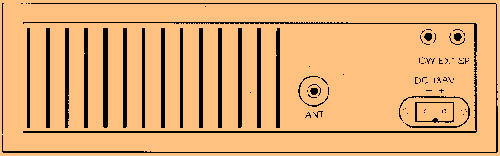
The DC power cable that connects to the transceiver's rear panel has a positive (+) red wire and a negative
(-) black wire. If you are installing the radio in a vehicle, it is recommended that you connect these wires
directly to the battery terminals. If this is not possible, use any convenient B + lead in the interior of the
vehicle and the negative frame. The transceiver has an internal DC filter that eliminates a large amount of
transient voltage spikes.
5. Connect the antenna.
You can operate the transceiver with any standard 50 ohm ground-plane, vertical, mobile whip, long wire,
or similar antenna. A standard SO-239 type connector is provided on the rear panel of the transceiver for
use with a PL-259 antenna connector.
A ground-plane antenna provides greater coverage and is ideal for base station to mobile operation since it
is essentially non-directional. From base station to base station, or point to point operation, a directional
beam operates at greater distances even under adverse conditions.
A non-directional antenna should be used in a mobile installation; a vertical whip antenna is best suited for
this purpose. The base loaded whip antenna normally provides effective communications. For greater
range and more reliable operation, a full quarter wave whip may be used. Either of these antennas use the
metal car body as a ground-plane. The shield of the base as well as the metal case of the transceiver
should be grounded.
6. Attach the microphone to the radio.
A high quality, dynamic microphone is supplied with the Ranger transceiver. Simply plug it into the jack
provided on the front of the transceiver. To transmit, press the PTT (Press-to-Talk) button; release the
button receive.
NOTE
The rear panel of the transceiver includes connections for an optional external speaker and CW key device.
Once installed, your transceiver is ready to use. The frequency range is preset at 28.000.0 to 29.999.9
MHz and the radio automatically scans in 100 Hz increments. Basic operation using these pre-established
settings is described below.
The Ranger provides the flexibility to change these settings, scan only your favorite frequencies saved in
memory, and use the split frequency feature. These advanced methods of operation also are described in
this section.
NOTE
Many of the controls described in this section perform multiple functions. For a detailed description of each
control, refer to the CONTROLS AND FUNCTIONS section
Basic Scanning
To turn on the transceiver and scan the full frequency range in 100 Hz increments, follow these steps:
1.
Turn on the backup voltage power. (Turn the RESET control clockwise until you hear a click.)
2.
Turn on the transceiver power. (Turn the AF GAIN control clockwise until you hear a click.)
3.
Turn the mode selector to the operating mode you want to use (FM, AM, USB, LSB, CW).
4.
Press the UPPER SCAN switch to scan the full frequency range from its lower limit (28.000.0) to the
upper limit (29.999.9). Press the LOWER SCAN switch to scan the frequency range from its upper
end to the lower end.
You'll notice that when the radio reaches either the upper or lower limit of its range, it automatically
goes to the other range limit (rollover) and continues scanning in the same direction (up or down).
You can change scanning direction whenever you wish by pressing either the UPPER or LOWER
SCAN button.
5.
If the radio does not begin scanning immediately, adjust the SQ (squelch) control clockwise until the
frequency display begins to change.
Use SQ to silence background noise; turn the control clockwise until the noise disappears. This also
reduces the Ranger's ability to receive weaker frequencies. To pick up more frequencies, turn SQ
counter-clockwise.
Variations on Basic Scanning Change Scanning Increment:
The Ranger is preset to scan at 100 Hz increments. You can change the scanning increments by pressing
the appropriate switch on the front panel while the transceiver is scanning.
For example, to scan in 10,000 Hz increments, press the upper 10K switch. The radio immediately begins
scanning in 10,000 Hz increments.
You can change the scanning increment whenever you wish while scanning.
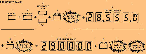
Change Frequency Range:
The full scanning range of the radio is 28.000.0 to 29.999.9 MHz. You can restrict the scanning range as
follows:
1.
Press the MANUAL button. (if the transceiver was scanning when you pressed this button, the
scanning stops.)
2.
Press SCAN PRG.
3.
Using the momentary switches below the frequency display, enter the scanning increment you want to
use (e.g., 100 Hz, 1K, 10K). You must enter the scanning increment before setting the frequency
range. Be sure to press the upper switch.
4.
Press ENTER. The frequency display will flash once.
5.
Enter the desired lower end frequency using the momentary switches. Each switch corresponds to the
LED (light emitting diode) above it. Press the upper momentary switch to increase the number, press
the lower switch to decrease the displayed number. The display will change as you enter each
number.
HELPFUL HINT: If the frequency you want to enter is greater than the one currently displayed, it is
best to enter the numbers from right to left. If the desired frequency is lower than the one currently
displayed, work from left to right.
6.
Press ENTER. The display will flash.
7.
Enter the upper end of the frequency range you want to set using the same switches as described in
step 5.
NOTE: You can enter either the upper or lower frequency range first.
8.
Press ENTER. The frequency display will flash twice.
9.
"Press upper or lower scan button to start scanning.
10.
If you wish to delete a certain frequency from within the scanning range selected, simply press the
cancel switch while the radio is on that frequency. This procedure may be used for deleting up to five
different frequencies.
NOTE: Radio must be in scan mode during this operation.
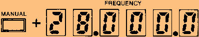
Enter a Specific Frequency:
You can manually select a specific frequency without scanning.
1.
Press MANUAL.
2.
Use the momentary switches to enter the frequency. Each switch corresponds to the LED above it.
Press the upper switch to increase the displayed number; press the lower switch to decrease the
number.
Using the Memory
The computer control features of the Ranger allows you to save your favorite frequencies in the
transceiver's memory. You can assign specific frequencies to any of 5 channels and then scan only those
channels using the MEMORY button.
Storing a Frequency in Memory:
To assign a frequency to a specific channel and store it in memory, follow these steps:
1.
Press MANUAL.
2.
Enter the desired frequency using the momentary switches. Each switch corresponds to the LED
display above it. Press the upper switch to increase the displayed number; press the lower switch to
decrease the number.
3.
Press ENTER. The display flashes once.
4.
Press the upper switch for the channel (CHI, CH2, ... CH5) to correspond with this frequency.
5.
Press ENTER again. The display flashes twice and the channel LED flashes once.
6.
Repeat steps 2 through 5 for each frequency you want to save in memory.
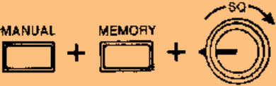
Scanning Memory
There are two methods to scan the frequencies you have saved in memory: manual or automatic. To
manually scan memory:
1.
Press MANUAL.
2.
Turn SQ counter-clockwise, but not off.
3.
Press MEMORY. Each time you press this button, the radio scans to the next channel in numerical
order (i.e., channel 1, channel 2, etc.). If you have not assigned frequencies to all five channels, the
radio scans only those channels that have been assigned a frequency.
TO MANUALLY SCAN MEMORY:
To automatically scan memory:
1.
Press MANUAL.
2.
Press MEMORY once.
3.
Turn SO clockwise until the transceiver beings to scan the channels automatically. The frequency
display will change and the channel LEDs will light briefly as each saved frequency is scanned. The
Ranger always scans the frequencies saved in memory in numerical order according to the channel
number (i.e., channel 1, channel 2, etc.).
4.
To stop automatic scanning, turn SO counter-clockwise or press MANUAL.
TO AUTOMATICALLY SCAN MEMORY:
Cancel a Frequency Saved in Memory:
If you have saved a frequency and assigned it to a specific channel, you also can cancel it. Once canceled,
it is no longer saved in the transceiver's memory. To cancel a channel:
1.
Press MANUAL.
2.
Manually scan to the frequency you want to cancel using the MEMORY button.
3.
Press CANCEL.
NOTE: To cancel everything you have saved in memory, turn the RESET control off and back on again.
TO CANCEL A FREQUENCY SAVED IN MEMORY
Change a Channel Frequency:
You can change the frequency assigned to any channel by simply overwriting the previous frequency.
Follow the same steps described above under storing a Frequency in Memory. The channel will then be
assigned the new frequency instead of the old one.
Split Frequency Operation
You can transmit and receive on different frequencies and preset the frequencies you want to use. Once
set, the Ranger automatically goes to the transmit frequency when the PTT button is pressed. When the
PTT button is released, the transceiver goes to the receive frequency.
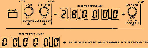
Preset the Receive and Transmit Frequencies:
1.
Press MANUAL.
2.
Make sure that the SPLIT, SPLIT PRG, and + buttons are out.
3.
Enter the receive frequency using the momentary switches. Each switch corresponds to the LED
display above it. Press the upper switch to increase the displayed number; press the lower switch to
decrease the number.
4.
Push the SPLIT PRG button in. The frequency display will change to all zeros (0).
NOTE
If you have previously programmed split frequency operation, the last split you entered will be displayed
(instead of zeros) when you press SPLIT PRG.
5.
Enter the difference between the receive and transmit frequencies using the momentary switches on
the front panel. For example, if the transmit frequency will be 1.5 MHz higher or lower than the receive
frequency, enter 1.500.0.
SPLIT FREQUENCY OPERATION
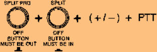
Use Split Frequency Operation:
1.
Turn SPLIT PRG off. Button should be out.
2.
Turn SPLIT on. Button should be in and the SPLIT LED on the front panel will light.
3.
Press + / - in if the transmit frequency will be higher than the receive frequency. The button should be
out if the transmit frequency is lower than the receive frequency by the increment entered during the
program procedure.
NOTE
The transceiver will not allow a transmit or receive frequency that is higher or lower than the upper limits of
the frequency range.
4.
Press the PTT button on the microphone to talk, release to receive. The transceiver displays the
transmit frequency when the button is pressed and the TX LED on the front panel will light. When the
button is released, the transceiver displays the receive frequency and the RX LED on the front panel
will light
NOTE
If you change the displayed frequency while using split frequency operation, the new frequency becomes
your receive frequency. When you press the PTT button to transmit, the transceiver splits from the current
frequency instead of the one you entered when you programmed split frequency operation.
5.
To discontinue split operation, release the SPLIT button (out position). The SPLIT LED will go out.
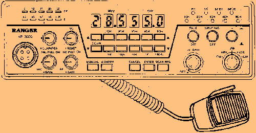
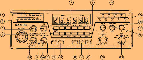
CONTROLS AND FUNCTIONS
The Ranger radio provides a variety of capabilities. To help you take advantage of those capabilities, the
front panel controls are designed for convenience and ease of use. Their functions are described below.
1.
RF LEDs indicate the amount of transmitted power. As the LEDs light across the scale, they show the
relative power of your transmission signal.
2.
S LEDs indicate the signal strength of the signal you are receiving. As the LEDs light across the scale,
they show the relative power of the signal.
3.
CLARIFIER is a fine tuning control. You can adjust a frequency - 500 Hz for best reception.
4.
RESET is on the on/off control for the radio's backup voltage power. When this control is turned on,
there is enough DC power to maintain any information you have saved in memory. Turn the control
clockwise until you hear a click to turn on the backup power. If you turn this control off, anything saved
in memory is erased.
SQ (squelch) is a second function of this control. Use it to silence the background (white) noise, to
adjust the transceiver's ability to receive signals, and to control automatic scanning of the memory.
Turn SQ clockwise to silence background noise. Turn SQ counter-clockwise to increase the Ranger's
ability to receive weaker frequencies. This control also starts and stops automatic scanning of
frequencies saved in memory. Turn SQ clockwise to initiate automatic scanning; turn it counter-
clockwise to stop automatic scanning of memory (after pressing the MEMORY button).
5.
MIC GAIN increases or decreases the power of the microphone amplifier circuit. To increase its gain,
turn the control clockwise; to decrease gain, turn the control counter-clockwise. For the optimum
setting, press the PTT button and turn the control clockwise until all RF LEDs light. Then, turn the
control counter-clockwise until the last LED just starts to flicker.
5A. ANL SWITCH -pull this knob to turn on automatic noise limiter.
6.
RF GAIN adjusts the transceiver's sensitivity to both signals and background noise. It affects the
distance at which you can receive a signal. Turn the control counter-clockwise to reduce the Ranger's
sensitivity. This is particularly useful in areas where there is a lot of congestion (many signals close
together on the frequency range).
6A. NB SWITCH -pull this knob to turn on noise blanker.
7.
The frequency display consists of eight (8) numerical LEDs. It displays the frequency in use from
28.000.0 MHz to 29.999.9 MHz.
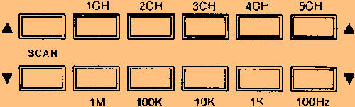
8.
The momentary switches are used for a variety of purposes described below:
SCAN Press upper switch to scan frequencies in an upward direction; press lower switch to scan
frequencies in decreasing order. 100K, 10K, 1K, 100Hz (scanning increments) Press the appropriate
upper momentary switch to select the scanning increment (i.e., 100,000 Hz, 10,000 Hz, 1,000 Hz, or
100 Hz).
To change the frequency displayed, press the upper switch to increase the displayed number or lower
switch to decrease the displayed number. Use the switches in this manner when selecting a specific
frequency, saving a frequency in memory, or setting frequencies for split frequency operation.
CH1, CH2, CH3, CH4, CH5 (channel selection) When saving a frequency in memory, press the upper
switch that corresponds to the channel number that you want to assign to that frequency.
9.
MANUAL is used before starting or restarting several procedures. If you are scanning frequencies,
scanning will stop when you press this button. Press MANUAL before directly entering a frequency,
before entering a new upper or lower frequency range limit, and before you begin the procedure for
storing frequencies in memory or setting frequencies for split operation.
10.
MEMORY scans the frequencies that you have saved in memory. If SQ is turned down (counter-
clockwise), MEMORY scans to the next channel each time the button is pressed. If SQ is turned up
(clockwise), channels are scanned automatically when the MEMORY button is pressed once.
11.
CANCEL clears a frequency that has been assigned to a channel and saved in memory. Use the
MEMORY button to display the frequency and press CANCEL.
12.
ENTER is used when you are changing the frequency range or saving frequencies in memory. Press
ENTER when you want the transceiver to accept the frequency displayed as the one you want to use.
For example, if you are changing the frequency range, press ENTER once after you enter the upper
frequency and again after entering the lower frequency. ENTER is used in the same way when saving
your favorite frequencies in memory.
13.
SCAN PRG is used when you want to change the frequency range of the transceiver. Press this
button before entering the new upper and lower range limits.
14.
Status LEDs provide the following information:
RX lights whenever the AF GAIN is on and the microphone's PTT button is released.
TX lights when you are transmitting (i.e., pressing the PTT button on the microphone).
ST BY is not currently implemented. This LED will be used when additional accessories are available.
SPLIT lights when you are using split frequency operation (the SPLIT button is pressed in).
15.
Channel LEDs (CH 1, CH2, CH3, CH4, CH5) provide information about frequencies saved in memory.
An LED flashes once when you save a frequency in memory by pressing one of the channel switches.
When you scan memory automatically, each LED lights briefly as the channel's frequency is scanned.
A channel's LED also lights when manually scanning memory and when that channel's frequency is in
use.
16.
SPLIT is pressed in when you want to use split frequency operation. Release the button (out position)
when you want to resume normal operation.
17.
SPLIT PRG is used when setting the frequencies for split frequency operation. The button should be
out when you enter the receive frequency. Press SPLIT PRG in before entering the difference
(number of MHz) between the receive and transmit frequencies. This button should be out when
actually using split frequency operation.
18.
+ / - is used with split frequency operation. The button should be out when you are setting the receive
and transmit frequencies. During actual operation, press the button in if the transmit frequency is
higher than the receive frequency. The button should be out if the transmit frequency is lower than the
receive frequency.
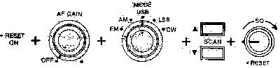
19.
OFF/AF GAIN is the on/off and volume control for the Ranger. Turn the control clockwise until you
hear a click to turn on the transceiver. Continue to turn the control clockwise to increase the volume;
turn it counter-clockwise to decrease the volume.
20.
MODE SELECTOR is used to select one of the following operating modes: FM (F3) Frequency
Modulation AM (A3) Amplitude Modulation USB (A3J) Upper Side Band LSB (A3J) Lower Side Band
CW (Al) Continuous Wave


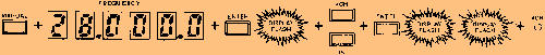
STORING A FREQUENCY IN MEMORY
ENTER A SPECIFIC FREQUENCY


© CB World Informer Network 1996 - 2023 Worldwide Rights Reserved

February
2002 Web
Edition


- August 1996
- September 1996
- October 1996
- November 1996
- December 1996
- Review Of Midland 79-290 AM/SSB Mobile
- Cobra/Uniden SSB Chassis Mod UPDATE
- Clarifiers
- President Jackson Unlocked Clarifier Mod.
- Cobra 148 & Uniden GrantXL Clarifier Mod.
- Cobra 142GTL & Uniden Washington Clarifier
- Uniden Grant Unlocked Clarifier Mod.
- Uniden PCI22 PRO SSB Clarifier Mod.
- Review Of The Northstar DX880HL
- Big Bust At The Consumer Electronics Show
- Bob's CB Has Opened
- January 1997
- The New Mongoose Model 450 Review
- Wilson Antenna Tests The Trucker 5000
- A Company With Interference Solutions
- Solving Telephone RF Interference
- Lowpass Filters: What, Where, And How
- Using Highpass Filters For TVI
- How To Conduct A Noise Audit
- Modern Do-It-Yourself Grounding Techniques
- Using Water Pipes For RF Grounding
- Using Water Pipes For RF Grounding
- February 1997
- The New Emperor TS-3010 Review
- Bulkhead Grounding
- Grounding Coaxial Cable Shields
- Using Anti-Oxidants
- Modern Lightning Protection - RF Entry Ports
- Modern Lightning Protection - AC Power Lines
- Modern Lightning Protection - Control Lines
- Modern Lightning Arrestors - Polyphaser VS I.C.E.
- Modern Lightning Arrestors - Alpha Delta VS I.C.E.
- Modern Lightning Arrestors - Cushcraft VS I.C.E.


- July 2001
- Galaxy DX 2547 Reveiw
- Inside The DX 2547
- DX 2547 Channel Mod
- DX 2547 Clarifier Mod
- DX 2547 Photos
- DX 2547 Manual Excerpts
- The Anttron Story
- Anttron 305 Revisited
- New Antrron Products
- Aries A-SWR 460 Digital Meter
- Barjan Buys Wilson Antenna
- Wilson Electronic In Cell Phone Market
- First Web Issue
- Help Get The Word Out
- August 2001
- Sneak Preview: The New Maverick A24
- Maverick A24 Front Panel Controls
- Maverick Conversion
- Inside The Magnum Maverick A24
- Barjan Buys Francis Antenna
- Wilson Antenna, 1 Year After Barjan Buyout
- CBer Busted
- Astaic's MobileMax
- Solarcon I-Max 2000
- False Performance Claims
- CAUTION: Don't Burn Out That Radio
- Magnum's Filtered Power Cord
- Dragon Super Heavy Duty SO-239 Stud
- CBWI...Give Us Your Opinion
- September 2001
- Reveiw Of The RCI 2950DX
- RCI 2950DX Image Rejection Modification
- RCI 2950DX Coversion & Clarifier Mods
- RCI 2950DX Photos
- RCI 2950DX Board Component Layout
- RCI 2950DX Adjustment Layout
- RM-9807: Petition To Remove 155 Mile Limit
- Slip-Seat Radio Box
- RF Limited UTB-1 Adjustable Talkback Board
- A Message From The Editor
- October 2001
- November 2001
- December 2001
- January 2002
- February 2002
- July 2002
- June 2014