Galaxy DX 2547 Service Manual Excerpts
Support, support, support...The Galaxy support department was gracious enough to send the Galaxy Noise
Filter schematic with out a request! This is what is missing in most instances these days with large consumer
electronics companies. Their either to big to follow up on details, don't know were to get the information, or
plain don't care. Another reason for the lack of support for many radios is that the radios are designed, built
and documented off shore and shipped directly to the distributor. The distributor doesn't understand radio
technology nor do they understand end user customer support. All they see is the chance to make higher
profits by cutting out the important link between the factory over seas and themselves. Most of these radios
end up in yard sales or the trash soon after the purchase. Sure you can save a few bucks, but what do you
do when the thing quits or there is a technical design flaw. Who's out their to follow up on it. Don't think the
distributor or mail order company will. They'll drop it like a hot rock and find a new product to make profit on.
Not at Galaxy, they support their product 100% and beyond. To be honest there are a few companies that
support their products, but increasingly I see more products that are not supported at all. Have you ever tried
to get a service manual for the Uniden Washington base radio? They haven't supplied them for many years!
Need more be said?
Click On Picture For Close-up.
Galaxy Noise Filter Schematic
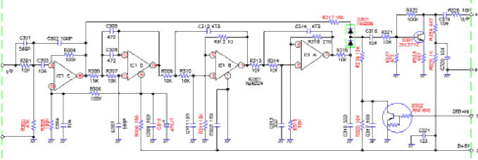

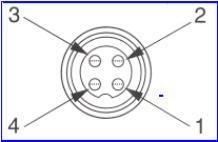
Figure 2-3 Transceiver Microphone Schematic.
Figure 2-4 Microphone plug and pin numbers
viewed from rear of pin receptacle.
The following information is from the Galaxy DX 2547 Service Manual supplied with the radio.


1.
DC Power Supply (13.8VDC, 10A)
2.
RF Wattmeter (100 MHz, SOW)
3.
Multimeter (Digital) Automatic
4.
Modulation Meter
5.
Audio Signal Generator
6.
Frequency Counter (100 MHz)
7.
RF Signal Generator (100 MHz)
8.
Automatic Distortion Meter
9.
Oscilloscope (50 MHz)
10.
Sinad Meter
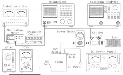
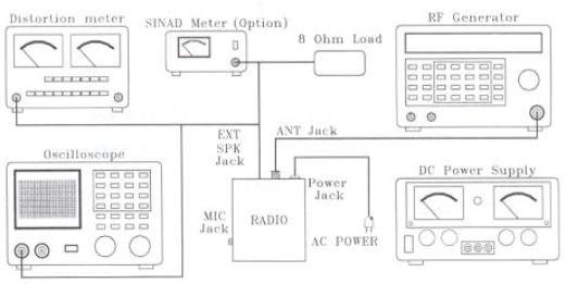
This transceiver has been aligned at the factory and does not require any adjustments at installation. The
required test equipment listed is used for the test setup or alignment shown in Figure 4-1 Transmitter Test
Setup and Figure 4-2 Receiver Test Setup. This test setup is used in part or total during the following
adjustments. Refer to Page 43 for adjustment location.


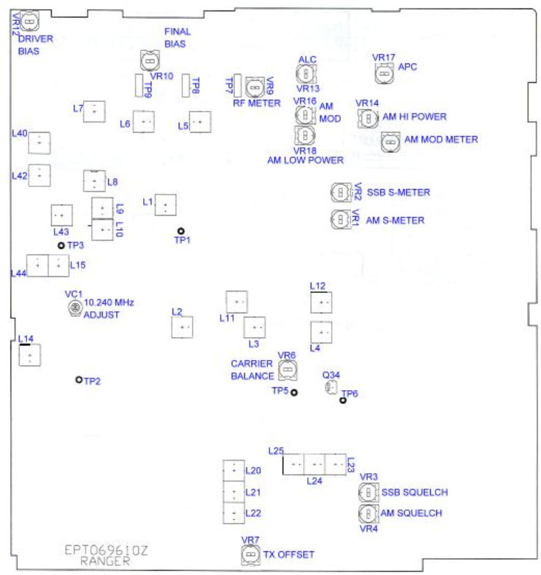
The Galaxy service manual has many more diagrams including circuit board layouts, block diagram and
schematics. Only a small sample have been included in this issue to give the reader a feel for how good
the manual is. The manual is professional in every way and will be an valuable asset to anyone who works
on the DX 2547.
I don't know for a fact, but judging by Galaxy's past history, much of the manual will probably be available
on their site before you know it. ©
CBWI

© CB World Informer Network 1996 - 2023 Worldwide Rights Reserved

July
2001 Web
Edition


- August 1996
- September 1996
- October 1996
- November 1996
- December 1996
- Review Of Midland 79-290 AM/SSB Mobile
- Cobra/Uniden SSB Chassis Mod UPDATE
- Clarifiers
- President Jackson Unlocked Clarifier Mod.
- Cobra 148 & Uniden GrantXL Clarifier Mod.
- Cobra 142GTL & Uniden Washington Clarifier
- Uniden Grant Unlocked Clarifier Mod.
- Uniden PCI22 PRO SSB Clarifier Mod.
- Review Of The Northstar DX880HL
- Big Bust At The Consumer Electronics Show
- Bob's CB Has Opened
- January 1997
- The New Mongoose Model 450 Review
- Wilson Antenna Tests The Trucker 5000
- A Company With Interference Solutions
- Solving Telephone RF Interference
- Lowpass Filters: What, Where, And How
- Using Highpass Filters For TVI
- How To Conduct A Noise Audit
- Modern Do-It-Yourself Grounding Techniques
- Using Water Pipes For RF Grounding
- Using Water Pipes For RF Grounding
- February 1997
- The New Emperor TS-3010 Review
- Bulkhead Grounding
- Grounding Coaxial Cable Shields
- Using Anti-Oxidants
- Modern Lightning Protection - RF Entry Ports
- Modern Lightning Protection - AC Power Lines
- Modern Lightning Protection - Control Lines
- Modern Lightning Arrestors - Polyphaser VS I.C.E.
- Modern Lightning Arrestors - Alpha Delta VS I.C.E.
- Modern Lightning Arrestors - Cushcraft VS I.C.E.


- July 2001
- Galaxy DX 2547 Reveiw
- Inside The DX 2547
- DX 2547 Channel Mod
- DX 2547 Clarifier Mod
- DX 2547 Photos
- DX 2547 Manual Excerpts
- The Anttron Story
- Anttron 305 Revisited
- New Antrron Products
- Aries A-SWR 460 Digital Meter
- Barjan Buys Wilson Antenna
- Wilson Electronic In Cell Phone Market
- First Web Issue
- Help Get The Word Out
- August 2001
- Sneak Preview: The New Maverick A24
- Maverick A24 Front Panel Controls
- Maverick Conversion
- Inside The Magnum Maverick A24
- Barjan Buys Francis Antenna
- Wilson Antenna, 1 Year After Barjan Buyout
- CBer Busted
- Astaic's MobileMax
- Solarcon I-Max 2000
- False Performance Claims
- CAUTION: Don't Burn Out That Radio
- Magnum's Filtered Power Cord
- Dragon Super Heavy Duty SO-239 Stud
- CBWI...Give Us Your Opinion
- September 2001
- Reveiw Of The RCI 2950DX
- RCI 2950DX Image Rejection Modification
- RCI 2950DX Coversion & Clarifier Mods
- RCI 2950DX Photos
- RCI 2950DX Board Component Layout
- RCI 2950DX Adjustment Layout
- RM-9807: Petition To Remove 155 Mile Limit
- Slip-Seat Radio Box
- RF Limited UTB-1 Adjustable Talkback Board
- A Message From The Editor
- October 2001
- November 2001
- December 2001
- January 2002
- February 2002
- July 2002
- June 2014


