
General Features
·
Bright 5" Color TFT Display w/ 800 x 480 Resolution
·
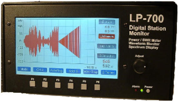
LP-700 has a larger enclosure and a 7" Display, otherwise the two meters are the same.
·
32-bit Main Processor
·
Touchscreen controls of all functions, plus physical switches for the six main function keys
·
Graphics and Audio coprocessors
·
(8) 16-bit / 200 ksps ADCs with Adjustable Oversampling
·
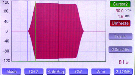
Low Distortion Proprietary Custom Digital Test Signals to Aid in Rig & Amplifier Adjustments
using WFM and Spectrum Displays.
·
Distinctive Aural/Visual Alarms for Each Channel for both Power and SWR.
·
Native USB Interface - No Drivers Needed(not needed for normal operation)
·
Flash Upgrade-able
·
Includes Windows based "VM" (Virtual Meter) software which allows computer control and
monitoring of the LP-500 locally, or remotely using RDP or a USB Device Server.
·
Fast Screen Refresh
·
12VDC Operation / 800 mA maximum.
·
Interface to Rig is Through Remotable RF Couplers using CAT5/6 cable of any practical
length.
·
Provides Extensive Information About the Quality of Your Transmissions
·
Size: LP-500: 9.125"W x 6.1"D x 4.88"H (23.2cm x 15.5cm x 12.4cm) LP-700: 10.125"W x
6.1"D x 5.63"H (25.7cm x 15.5cm x 14.3cm)
Watt / SWR Meter Features
·
Couplers for HF, VHF, UHF... Power up to 10KW(VHF / UHF available soon)
·
Up to 4 Couplers with Simultaneous Sampling & Auto-Ranging
·
NIST Traceable Calibration
·
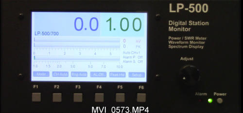
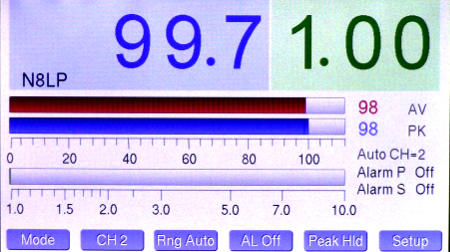
Large Numerals for Power and SWR at a Glance
·
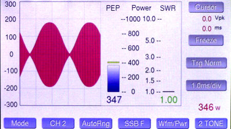
Simultaneous Bargraphs for Instantaneous Peak Pwr, Average Pwr & SWR
·
Sticky" bar displays highest peaks in all modes
·
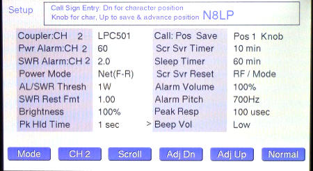
Flexible Multi-Channel SWR & Power Alarms w/ Adjustable Set Points
·
SWR Protection Relay Jacks for 2 Amplifiers
·
Optical Encoder Adjusts Averaging Time (Fast, Medium, Slow) Waveform Monitor
Scope Features
·
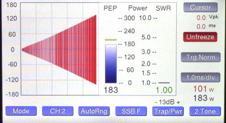
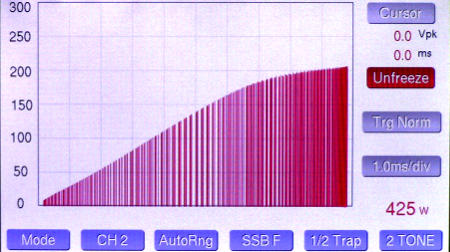
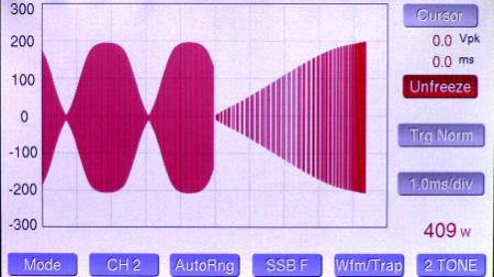
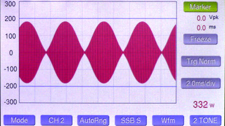
Full screen Waveform, Trapezoid & Scope Displays(Trapezoid requires two couplers)
·
Adjustable Sweep and Trigger with Memory
·
5 Presets for SSB, CW, PSK plus 3 User Selections
·
10 Vertical Scales per Channel with Memory
·
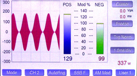
Multiple "Split-Screen" Displays with Combinations of Waveform, Power/SWR, Trapezoid
and AM Modulation (w/ Bargraphs/Readouts for Positive & Negative Peaks)
·
Touch Screen Cursors for Measuring Time Intervals & Levels
·
Adjustable Peak Markers to Show Preset Power Limits
·
Freeze Button to Facilitate Touch Screen Measurements
·
Optical Encoder for Adjusting User Sweep Presets and Trapezoid Horizontal Gain (Width).
Spectrum Display Features
·
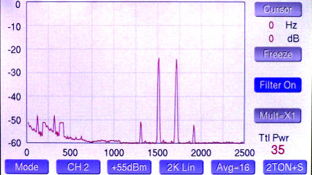
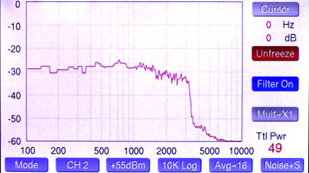
Displays Modulation Spectrum of Transmitted Signal, as sampled by the coupler *
·
Adjustable Span & Averaging
·
Linear and Log Frequency Scales
·
Adjustable Vertical Reference with +65, +55 & +45 dBm Full Scale
·
18 bits Effective Resolution
·
Up to 80 dB Measurement Range
·
Touch Screen Cursors for Measuring Frequencies & Levels
·
Adjustable Peak Level Marker
* The Spectrum display does not sample RF directly, so results cannot be compared directly to an RF spectrum analyzer. Useful
comparative measurements can be made, however. Because the couplers employ diode envelope detectors, signals without a
carrier would normally be distorted during demodulation. To account for this, we provide special test signals for these modes which
add subcarriers to simulate the existence of a carrier. See usage guidelines in the User Guide for more details. While the LP-100A
couplers look similar to the LP-500 couplers, they are completely different and are therefore not compatible. Important notice for
LP-100A owners: LP-500 will not replace the LP-100A. The LP-100A will continue with some important features not provided in the
LP-500.
Specifications… (with LPC-501 coupler) Subject to change without notice.
General
Power Range
0.1W to 3KW PEP (1500W Average)
Absolute Power Accuracy
+/- 5% at 7 MHz, 10 to 1500W.
Flatness
Better than +/- 3% from 1.8 to 54 MHz (+/- 1% typical from 1.8 to 30 MHz)
Directivity
>30 dB, 1.8 to 54 MHz
Return Loss
>30 dB, 1.8 to 54 MHz
SWR Range
1.00 to 9.99
SWR Accuracy
~5%
Bar Graph Resolution
600 steps for each range, Manual or Auto-Ranging
Number of Channel
8 simultaneous (FWD & REF power for 4 couplers)
Channel Balance
+/- 0.1%
Memories
Range & Alarm settings are saved per channel Channel settings are saved per mode
A/D Converter
16-bit / 200ksps, plus oversampling (2X to 16X).
DAC Resolution
18-bit, 96 dB SNR
Screen Refresh
5 Hz to 70 Hz, depending on mode, sweep/span settings.
Sampling Rate
2.5k to 80 ksps, depending on mode, sweep/span settings.
Display Resolution
800 x 480 pixels (WVGA)
Display Type
TFT with White LED Backlight
Display Size
LP-500: 5" Diagonal, LP700: 7" Diagonal
Test Tone Output
250 ohms, 350-500mVpp, unbalanced, 0.01% THD into 10K load
Power Requirements
12-16VDC @ 800 mA maximum
Scope
Sweep Rate
1.0 to 20.0 ms/division in 0.1 ms steps Factory Presets and 3 User Adjustable Presets
Display Modes
7, including 4 split screens
Trigger Modes
Normal, Plus, Minus, Plus/Minus, Free Running
AM Modulation %
0 to 150, positive. 0 to 100 negative
Cursors
2, measuring peak voltage and time (ms)
Markers
1 or 2, adjustable to show preset power limits
Spectrum
Frequency Spans
2.5, 5.0 & 10.0 kHz, w/linear or log scaling
Span Multiplier
5X (500 & 1000 Hz, linear)
RBW
1 to 20 Hz, depending on span
Averaging
2X to 16XFull Scale Reference
+45, +55, +65 dBm
ADC Dynamic Range
> 90 dB
Coupler Dynamic Range
Up to 80 dB, depending on modulation type
Cursors
2, measuring peak power (dBm) and frequency (Hz)
Markers
1, adjustable to show preset power limit
Additional Couplers
LPC-502
Range
5KW PEP / 2500W average
Flatness
+/- 3% from 1.8 to 54 MHz (+/- 2% typical from 1.8 to 30 MHz)
Directivity
>30 dB for 1.8 to 54 MHz
Return Loss
>30 dB from 1.8 to 54 MHz
LPC-503
Range
10KW PEP / 5KW Average
Flatness
+/- 5% from 1.8 to 30 MHz (+/- 3% typical from 1.8 to 30 MHz)
Directivity
>30dB from 1.8 to 30 MHz
Return Loss
>30dB from 1.8 to 30 MHzL
PC-504
Range
3KW PEP / 1.5KW Average
Flatness
+/- 1% from 144 to 148 MHz
Directivity
>30dB from 144 to 148 MHz
Return Loss
>30dB from 144 to 148 MHz
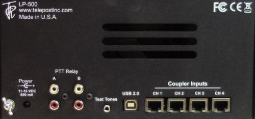
Connections:
Power: 12-16 VDC @ 800 mA maximum, center pin positive, 5.5mm OD / 2.5mm ID. The supplied cable either has a white stripe on the
positive wire, or ridges on the negative wire, depending on the cable supplied. The meter has a protection diode to prevent damage in case of
reverse polarity. The meter also has a built in replaceable 1A automotive type plugin fuse on the PCB for protection. We recommend a well
regulated supply with a 1A to 1.5A rating. After much testing, we found an inexpensive linear (not switching) supply that is very clean. We
offer these for sale for $15. An alternative is to use the accessory 12VDC jack on the rig if it can supply the current. You can also use a
12VDC power distribution strip like RigRunner connected to the main station DC supply. When sharing a power supply with the LP-500 and
rig, make sure that the supply, rig and meter are all bonded together with heavy wire or copper braid. If there is any residual DC voltage on
the ground lead to the meter, it can add noise to the scope displays and increase the power and SWR readings. Using a separate supply like
the one mentioned above avoids the problem, but it’s still a good idea to bond all your equipment together.
PTT: For older amplifiers, loop the PTT (send, amp keying) between your amplifier and rig through the LP-500 using RCA cables. Two
isolated pairs of connectors are provided for connecting two amplifiers. Use either pair for either amplifier.
USB 2.0: Connects to computer using standard USB cable (Type A to Type B connectors). Used for flashing firmware and interfacing to LP-
500 VM and future utility program. Can be connected to USB 2.0 or 3.0 jacks on PC. No special drivers are necessary since the standard
Windows drivers are used. Windows should automatically recognize the LP-500 as USB HID (Human Interface Device).
Couplers: Connect to corresponding jacks on the coupler(s) using supplied or user provided CAT5/6 shielded Ethernet cables. Unshielded
(UTP) cables are probably acceptable as well. See Fig.1 on page 3.
Test Tones: Audio output for built in test tones. 3.5mm mono. Connects to the MIC or LINE input of the rig. An attenuator will be needed in
the case of mic input, and possibly galvanic isolation (transformer). Interfaces designed for a sound card based RTTY setup can work for this.
To minimize ground potential differences between the meter, rig and power supplies, it is recommended that they all be bonded together with
heavy wire or copper braid. This will minimize pickup of noise on the test signal displays.
Line Level… Most rigs have a high Z (10K) line input designed for sound card based digital modes. These inputs work well for the LP-500
test tones. One some rigs they are labeled as line inputs, and have dedicated RCA or 1/8” (3.5mm) jacks. On some rigs they are part of an
ACCessory jack or a DATA jack. These are generally DIN type connectors. Consult your user manual for specifics.
Mic Level… There are some inexpensive “sound card” interfaces available to converting line level outputs to mic level rig inputs, with level
adjustment and isolation. Devices in this category include the W2IHY iBox, RigBlaster Nomic ($60USD) and several interfaces from MFJ, like
the MFJ-1273 and -1275 series. I have tested these and found that they can provide proper levels to the rig mic jack, and minimize the effects
of multiple ground returns. These devices do not utilize magnetically shielded transformers, so it is important to not place them near power
supplies with large transformers. We will be publishing a help file on the LP-500 web page detailing methods to avoid pickup of these signals.
In the meantime, you can check out the discussion “clean up 2 tone signal” on the LP-500 User Group or extensive info published by Jim
Brown, K9YC,http://audiosystemsgroup.com/HamInterfacing.pdf
Creating your own test tones... In addition to the built in tones, you can create your own tones and save them to the micro SD card
inside the LP-500. The card uses the FAT16 file format, and the files must be named USER0001.wav through USER0004.wav. The
wave format should be 16-bit, 44.1 kHz sampling rate. Remove the card and plug it into a PC to save the new files. It's located on the
audio daughter card near the test tone output jack. The files can be any valid wave file, including voice.

© CB World Informer Network 1996 - 2023 Worldwide Rights Reserved


- August 1996
- September 1996
- October 1996
- November 1996
- December 1996
- Review Of Midland 79-290 AM/SSB Mobile
- Cobra/Uniden SSB Chassis Mod UPDATE
- Clarifiers
- President Jackson Unlocked Clarifier Mod.
- Cobra 148 & Uniden GrantXL Clarifier Mod.
- Cobra 142GTL & Uniden Washington Clarifier
- Uniden Grant Unlocked Clarifier Mod.
- Uniden PCI22 PRO SSB Clarifier Mod.
- Review Of The Northstar DX880HL
- Big Bust At The Consumer Electronics Show
- Bob's CB Has Opened
- January 1997
- The New Mongoose Model 450 Review
- Wilson Antenna Tests The Trucker 5000
- A Company With Interference Solutions
- Solving Telephone RF Interference
- Lowpass Filters: What, Where, And How
- Using Highpass Filters For TVI
- How To Conduct A Noise Audit
- Modern Do-It-Yourself Grounding Techniques
- Using Water Pipes For RF Grounding
- Using Water Pipes For RF Grounding
- February 1997
- The New Emperor TS-3010 Review
- Bulkhead Grounding
- Grounding Coaxial Cable Shields
- Using Anti-Oxidants
- Modern Lightning Protection - RF Entry Ports
- Modern Lightning Protection - AC Power Lines
- Modern Lightning Protection - Control Lines
- Modern Lightning Arrestors - Polyphaser VS I.C.E.
- Modern Lightning Arrestors - Alpha Delta VS I.C.E.
- Modern Lightning Arrestors - Cushcraft VS I.C.E.


- July 2001
- Galaxy DX 2547 Reveiw
- Inside The DX 2547
- DX 2547 Channel Mod
- DX 2547 Clarifier Mod
- DX 2547 Photos
- DX 2547 Manual Excerpts
- The Anttron Story
- Anttron 305 Revisited
- New Antrron Products
- Aries A-SWR 460 Digital Meter
- Barjan Buys Wilson Antenna
- Wilson Electronic In Cell Phone Market
- First Web Issue
- Help Get The Word Out
- August 2001
- Sneak Preview: The New Maverick A24
- Maverick A24 Front Panel Controls
- Maverick Conversion
- Inside The Magnum Maverick A24
- Barjan Buys Francis Antenna
- Wilson Antenna, 1 Year After Barjan Buyout
- CBer Busted
- Astaic's MobileMax
- Solarcon I-Max 2000
- False Performance Claims
- CAUTION: Don't Burn Out That Radio
- Magnum's Filtered Power Cord
- Dragon Super Heavy Duty SO-239 Stud
- CBWI...Give Us Your Opinion
- September 2001
- Reveiw Of The RCI 2950DX
- RCI 2950DX Image Rejection Modification
- RCI 2950DX Coversion & Clarifier Mods
- RCI 2950DX Photos
- RCI 2950DX Board Component Layout
- RCI 2950DX Adjustment Layout
- RM-9807: Petition To Remove 155 Mile Limit
- Slip-Seat Radio Box
- RF Limited UTB-1 Adjustable Talkback Board
- A Message From The Editor
- October 2001
- November 2001
- December 2001
- January 2002
- February 2002
- July 2002
- June 2014