CB World Informer Exclusive 4 Position Channel Mod
Before you start, make sure the radio isn't connected to a power source!
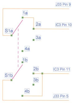
This is a 4 position rotary switch conversion
Reference Picture Below
1.
Remove the radio covers, all knobs, and front bezel.
2.
Remove the headphone jack from the front panel and leave wired.
3.
Heat shrink headphone jack and secure to inside of chassis with
double sided mounting foam. (See Figure 2)
4.
Turn the shaft of the rotary switch to position 2.
5.
Mount the switch in the hole for the headphone jack and position the
flat side of the shaft toward the bottom of the radio.
6.
Wire according to the schematic below (See Figure 1) and
reassemble the radio.
Figure 1
Figure 2


© CB World Informer Network 1996 - 2023 Worldwide Rights Reserved

July
2001 Web
Edition


- August 1996
- September 1996
- October 1996
- November 1996
- December 1996
- Review Of Midland 79-290 AM/SSB Mobile
- Cobra/Uniden SSB Chassis Mod UPDATE
- Clarifiers
- President Jackson Unlocked Clarifier Mod.
- Cobra 148 & Uniden GrantXL Clarifier Mod.
- Cobra 142GTL & Uniden Washington Clarifier
- Uniden Grant Unlocked Clarifier Mod.
- Uniden PCI22 PRO SSB Clarifier Mod.
- Review Of The Northstar DX880HL
- Big Bust At The Consumer Electronics Show
- Bob's CB Has Opened
- January 1997
- The New Mongoose Model 450 Review
- Wilson Antenna Tests The Trucker 5000
- A Company With Interference Solutions
- Solving Telephone RF Interference
- Lowpass Filters: What, Where, And How
- Using Highpass Filters For TVI
- How To Conduct A Noise Audit
- Modern Do-It-Yourself Grounding Techniques
- Using Water Pipes For RF Grounding
- Using Water Pipes For RF Grounding
- February 1997
- The New Emperor TS-3010 Review
- Bulkhead Grounding
- Grounding Coaxial Cable Shields
- Using Anti-Oxidants
- Modern Lightning Protection - RF Entry Ports
- Modern Lightning Protection - AC Power Lines
- Modern Lightning Protection - Control Lines
- Modern Lightning Arrestors - Polyphaser VS I.C.E.
- Modern Lightning Arrestors - Alpha Delta VS I.C.E.
- Modern Lightning Arrestors - Cushcraft VS I.C.E.


- July 2001
- Galaxy DX 2547 Reveiw
- Inside The DX 2547
- DX 2547 Channel Mod
- DX 2547 Clarifier Mod
- DX 2547 Photos
- DX 2547 Manual Excerpts
- The Anttron Story
- Anttron 305 Revisited
- New Antrron Products
- Aries A-SWR 460 Digital Meter
- Barjan Buys Wilson Antenna
- Wilson Electronic In Cell Phone Market
- First Web Issue
- Help Get The Word Out
- August 2001
- Sneak Preview: The New Maverick A24
- Maverick A24 Front Panel Controls
- Maverick Conversion
- Inside The Magnum Maverick A24
- Barjan Buys Francis Antenna
- Wilson Antenna, 1 Year After Barjan Buyout
- CBer Busted
- Astaic's MobileMax
- Solarcon I-Max 2000
- False Performance Claims
- CAUTION: Don't Burn Out That Radio
- Magnum's Filtered Power Cord
- Dragon Super Heavy Duty SO-239 Stud
- CBWI...Give Us Your Opinion
- September 2001
- Reveiw Of The RCI 2950DX
- RCI 2950DX Image Rejection Modification
- RCI 2950DX Coversion & Clarifier Mods
- RCI 2950DX Photos
- RCI 2950DX Board Component Layout
- RCI 2950DX Adjustment Layout
- RM-9807: Petition To Remove 155 Mile Limit
- Slip-Seat Radio Box
- RF Limited UTB-1 Adjustable Talkback Board
- A Message From The Editor
- October 2001
- November 2001
- December 2001
- January 2002
- February 2002
- July 2002
- June 2014